27
1
2
14
12
6
13
3
4
5
7
8
10
11
Fig. 2.4
9
Fig. 2.5
2
5
4
3
1
Tab. 2.12
Tab. 2.13
Fig. 2.3
ED0053030410
TECHNICAL INFORMATION
2.9.3 Injection pump
Pressure into the injection pump must be positive in all operating
conditions.
The injection pump is operated by means of the pump control
gear (Tab. 2.40 - Pos. 7) and sends high-pressure fuel to the
injectors.
NOTE: In the event of leakage from the high pressure circuit
do not intervene with the engine running, but turn it
off and wait 5 - 10 minutes before checking the leak.
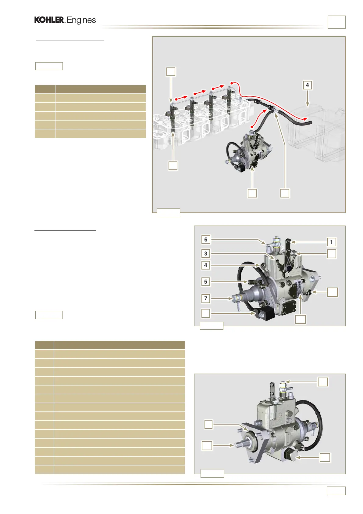
2.9.2 Fuel return circuit
The fuel return circuit is under low pressure.
POS. DESCRIPTION
1 Injectors
2 Injectors fuel return pipe
3 Injection pump
4 Fuel tank
5 Fuel return pipe to the tank
POS. COMPONENTS DESCRIPTION
1 Accelerator lever
2 Max adjustment
3 Min Adjustment
4 Torque adjustment
5 High pressure delivery to injectors
6 Return to fuel tank
7 Inlet suction fuel
8 Cold Start Advance
9 Gasket
10 Shaft
11 Advance settings (locked)
12 Pump identication label
13 Air bleeding screw
14 Pump control shaft blocking device
NOTE:
The representation of fuel tank is
purely indicative.
Component not necessarily supplied
by KOHLER.

 Loading...


