37
1
76
8
4 5
3
11
10
9
2
Fig. 2.25
Tab. 2.28
Fig. 2.26
Tab. 2.29
1 A8
3
2 4576
B
C
ED0053030410
TECHNICAL INFORMATION
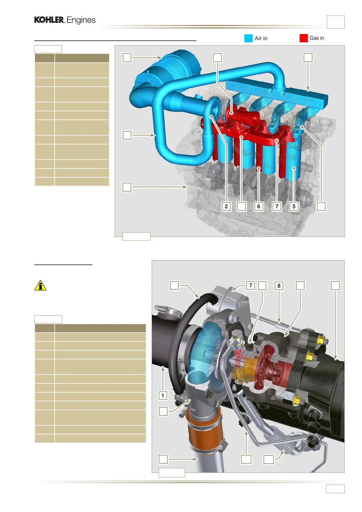
POS. DESCRIPTION
1 Air intake hose
2 Air compression volute
3 Turbo charger central body
4
Turbine housing with Waste Gate
valve
5 Gas exhaust ange
6 Waste Gate control valve hose
7 Waste Gate valve control actuator
8 Waste Gate control valve linkage
9
Air compressed ow pipe to
intercooler
10 Oil drain pipe
11 Turbo charger lubrication pipe
2.12.3 Turbocharger
The turbocharger is controlled by means of
exhaust gas that activates the turbine.
Important
• See Par. 2.19.
Air in intake
Gas in exhaust
POS. DESCRIPTION
1
Air in intake from air
lter
2 Air in compression
3
Air in intake
manifold ow
4 Air in head intake
5 Air in cylinder intake
6
Gas in cylinder
outlet
7 Gas in head outlet
8
Exhaust gas from
the turbocharger
A Intake manifold
B Exhaust manifold
C Crankcase
2.12.2 Diagram, intake and exhaust circuit without Intercooler

 Loading...


