36
1
378
2
9
7
B
10
C
D
4
5
1
Fig. 2.23
Fig. 2.24
4
6
A
Tab. 2.27
ED0053030410
TECHNICAL INFORMATION
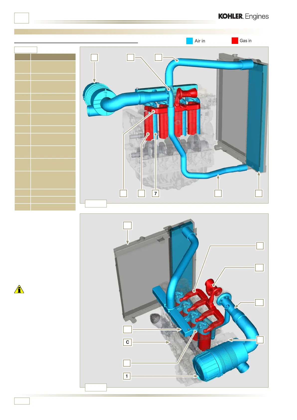
2.12 Intake and exhaust circuit
Air in intake
Gas in exhaust
Important
• The air temperature inside
the intake manifold must
never exceed that of the
environment by 10°C.
Clean air is sucked by means
of an intake manifold and
via ducts in the cylinder
head, enters the cylinders.
Compressed air inside the
cylinders and mixed with the
fuel transforms into Gas after
combustion. Gas is expelled
from the cylinders and sent to
the exhaust manifold, which
expels the gas towards the
exhaust mufer.
POS. DESCRIPTION
1
Air in intake from air
lter
2 Air in compression
3
Air in intercooler
ow
4 Air cooling
5
Air in intake
manifold ow
6
Cylinder head air
intake
7 Air in cylinder intake
8
Gas in cylinder
outlet
9
Cylinder head gas
outlet
10
Exhaust gas from
the turbocharger
A
Diagram, intake
and exhaust circuit
without Intercooler
B Exhaust manifold
C Crankcase
D Radiator/intercooler
2.12.1 Intake and exhaust circuit diagram with Intercooler

 Loading...


