45
Fig. 2.44
Fig. 2.46
E
D
G
P
L
W1
W2
W3
W4
W5
Fig. 2.47
M
S
Tab. 2.37
H
DF
Tab. 2.38
Tab. 2.39
°C HEATER CSA
≤ 20 ÷ -15 0"
120"
-16 16"
-21 21"
-26 26"
≤ -32 32"
Fig. 2.45
ED0053030410
TECHNICAL INFORMATION
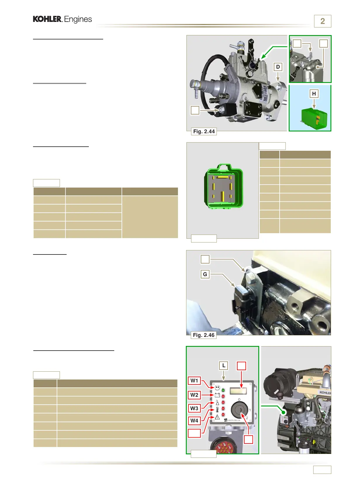
2.15.5 Cold Start Advance
The Cold Start Advance E devi ce is pa r t of injectio n pump D; it
provides for advance injection modication to enable advance
of the engine at low temperatures.
2.15.6 Electro-Stop
The electro-stop F device is part of injection pump D; it turns
off the engine by blocking the ow of fuel into pump D.
2.15.7 Fuse
Device G is assembled on cylinder head P (ywheel side);
it protects the electrical circuit in the event of an overload or
short circuit.
2.15.9 Control panel (optional)
Panel L can be assembled on the engine or machine.
In Tab. 2.39, are described the main functions are illustrated.
POS. DESCRIPTION
M Hour-meter indicator
S Control switch to start the engine
W1 Panel ignition indicator
W2 Warning Light - battery not charging
W3 Warning Light - engine oil not pressurised
W4 Warning Light - high coolant temperature
W5 Warning Light - alarm general indicator
NOTE:
Component not necessarily supplied by KOHLER.
NOTE:
Component not necessarily supplied by KOHLER.
POS. CONNECTED TO:
1 Heater
2 50 - ignition
3 15 - ignition
4 CSA
5 30 - battery
6 ...
7 Earth
8
Control panel
indicator
2.15.8 Start-up relay
The H device assists cold engine ignition controlling the "cold
starting device" (Heater) and the "Cold Start Advance" (CSA).
Tab. 2.37 indicates the activation times based on the ambient
temperature.

 Loading...


