93
Z
Fig. 8.3
K
W
X
Z1 W1
X1
K1Y1
Fig. 8.4
R
Y
S
Tab. 8.2
Tab. 8.3
S1
P
B
ED0053030410
INFORMATION ABOUT OVERHAULING
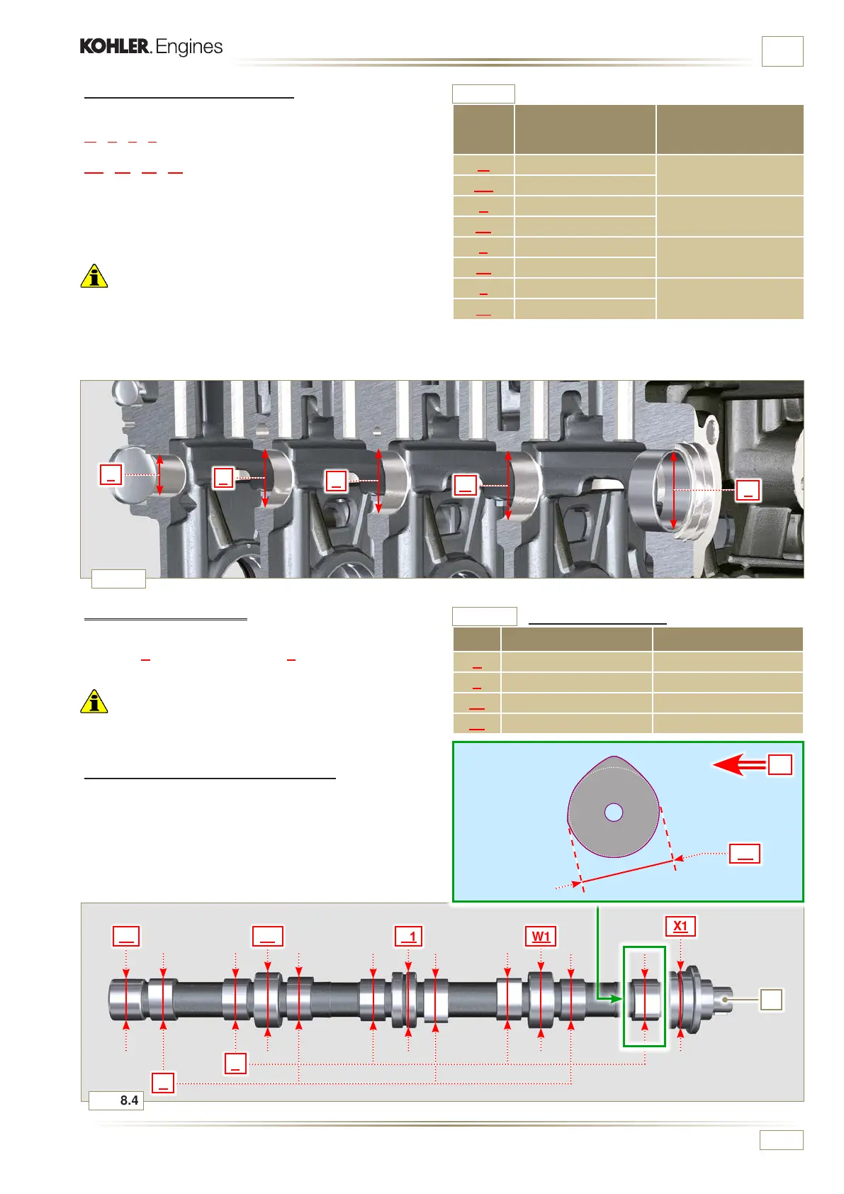
8.2.3 Camshaft housing check
Use an internal dial gauge to measure the diameters of housings
W - K - Y - Z.
With a micrometer, measure the diameters of gudgeon pins
W1 - K1 - Y1 - Z1 (Fig. 8.4).
According to the values measured, calculate the clearance
between the housing and gudgeon, which is to observe the
values in Tab. 8.2.
The MAX value of wear allowed is 0.120 mm.
Important
• Tab. 8.2 details the dimensional values of new components
only.
REF. DIMENSIONS (mm)
CLEARANCE
VALUE (mm)
W 47.500 - 47.525
0.060 - 0.105
W1 47.420 - 47.440
K 47.000 - 47.025
0.060 - 0.105
K1 46.920 - 46.940
Y 46.500 - 46.525
0.060 - 0.105
Y1 46.420 - 46.440
Z 35.000 - 36.025
0.060 - 0.105
Z1 34.920 - 35.940
8.2.4 Camshaft control
W i t h a m i c r o m e t e r, m e a s u r e t h e m a x i m u m d i m e n s i o n s o f i n t a k e
camshaft R and exhaust camshaft S (Tab. 8.3).
The MAX value of wear allowed is 0.1 mm.
Important
• Tab. 8.3 details the dimensional values of new components
only.
8.2.5 Camshaft control with internal EGR
The internal EGR is available only for Stage IIIA or Tier 3
eng ines provided w i th "CE" a pproval ( Par. 1.2) o r " EPA" name
plate (P a r. 1. 3). With a micrometer, measure the dimensions of
the S1 quota (Tab. 8.3) on all of cams S (the S1 quota varies
according to the code of camshaft P - refer to the spare parts
catalogue to identify the code of camshaft P). Replace camshaft
P if the S1 quota does not comply with the value on Tab. 8.3.
Housing and camshaft gudgeon dimensions.
REF. CODE (P) DIMENSIONS (mm)
R 40.495 - 40.433
S 39.175 - 39.113
S1 P = ED0010101820-S 35.666 - 35.616
S1 P = ED0010101730-S 35.564 - 35.514
Camshaft dimensions

 Loading...


