124
8
_07
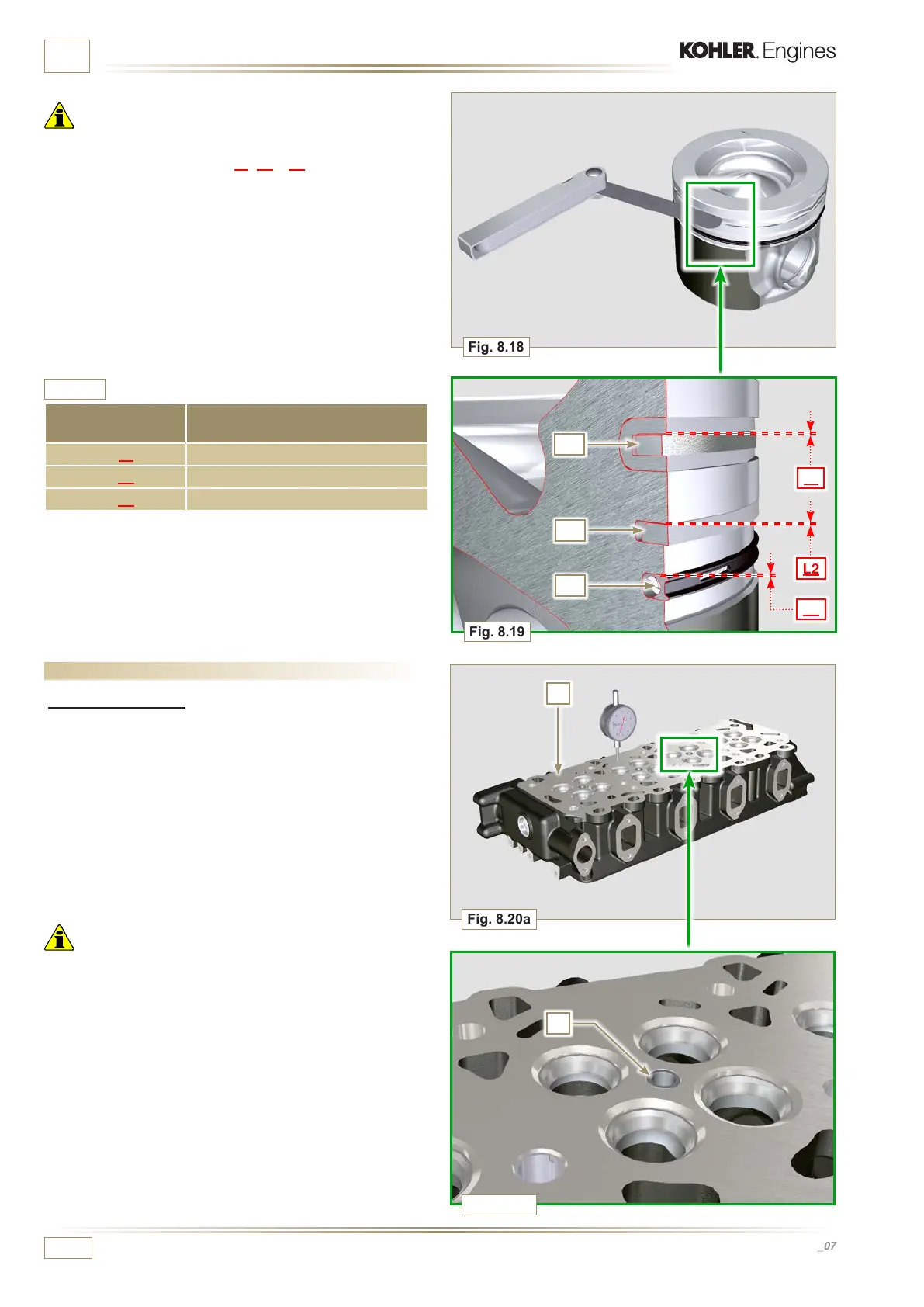
Fig. 8.18
Fig. 8.19
L1
L2
L3
U2
U1
U3
Fig. 8.20a
C
A
Fig. 8.20b
ED0053029590
INFORMATION ABOUT OVERHAULING
Tab. 8.8
SEAL RINGS CLEARANCE VALUE (mm)
U1 (L1) 0.110 - 0.150
U2 (L2) 0.070 - 0.115
U3 (L3) 0.030 - 0.065
8.6 Cylinder head
8.6.1 Flatness check
Put the cylinder head on a surface plate and, with a dial gauge,
check the atness of surface C.
The MAX value of allowable irregularity of surface C is 0.10
mm.
If the value is not observed, you are required to grind surface C.
The MAX removal allowed is 0.20 mm.
Important
• Grinding is to be performed with sleeves A of the electronic
injectors assembled.
• Grinding is prohibited on all engines provided with an EPA
name plate (refer to Par 1.3).
Important
• With a feeler gauge, measure the clearance of the seal ring
in the respective seat (value L1, L2 e L3).
• If the clearance does not comply with the values shown in the
table (Tab. 8.8), replace the seal rings and the piston.

 Loading...


