125
8
_07
Fig. 8.22
Z
Z1
Z2
B
C
Fig. 8.21
Fig. 8.23
D
E
GF H
ED0053029590
INFORMATION ABOUT OVERHAULING
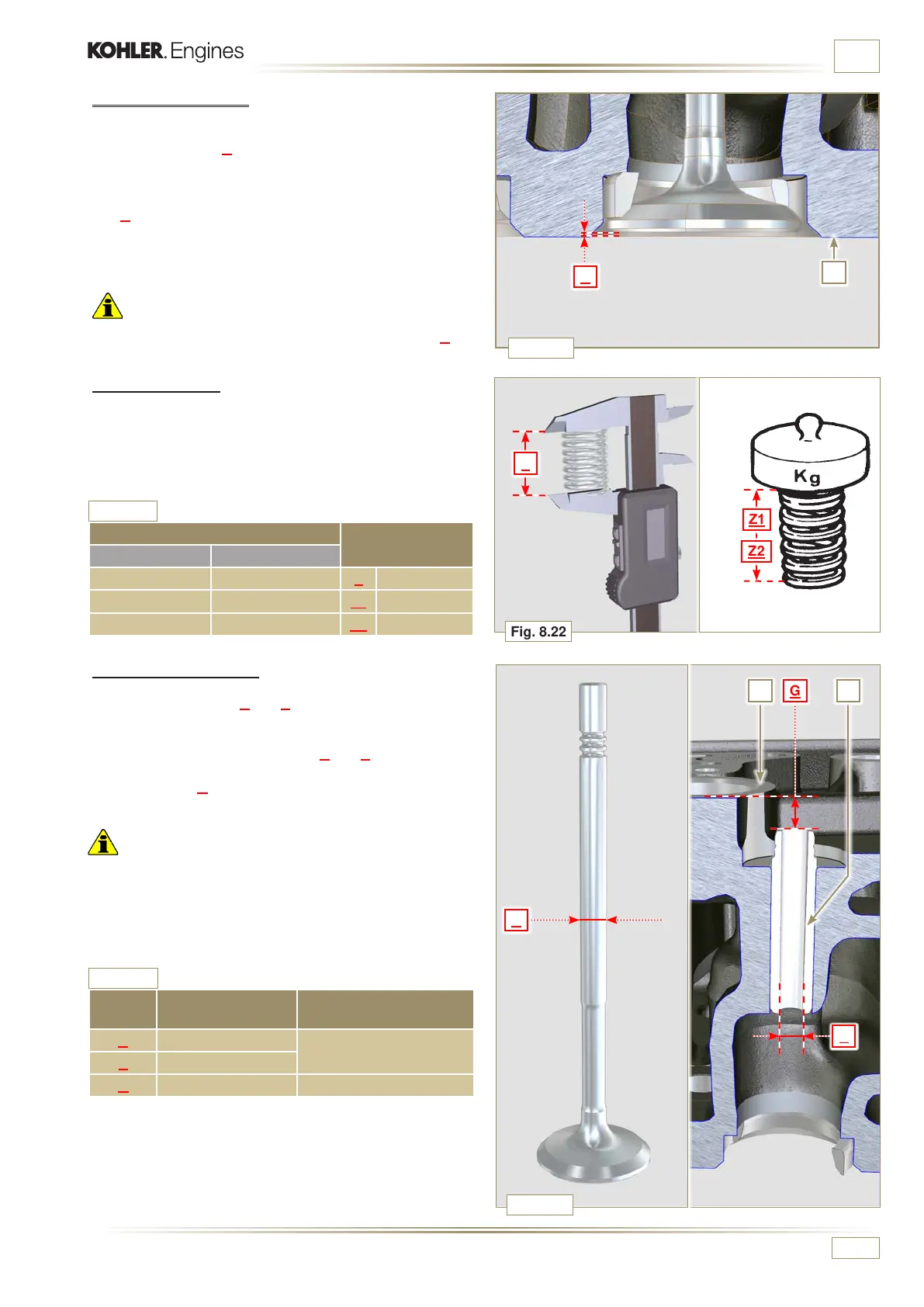
8.6.2 Valve seats check
Thoroughly clean the valves and their seats with.
Measure indentation B o f e a c h v a l v e w i t h r e g a r d t o t h e c y l i n d e r
head surface C, which is to be a MIN of 0.60 mm and MAX
of 0.85 mm.
The B MAX indentation allowed on worn components is 1.10
mm.
If the measured value does not correspond with the values
indicated, replace the worn component.
Important
• The seats must be worked after driving to reach value B, go
to a rectification workshop for such operations.
8.6.3 Valve springs
Using a dynamometer, subject the spring to two different
forces (in Tab. 8.9) and check that the length of the spring
corresponds to the values indicated in the table.
(*1)
T h e c o d e ED0057551850-S i s i n s t a l l e d f r o m S/N 44188 0176 0
Tab. 8.9
8.6.4 Valve guides check
Measure the diameters D and E of the rods and guides valve
(Tab. 8.10).
The MAX allowed value of wear for D and E is 0.10 mm.
Observe values G from surface F when assembling guides
H (Tab. 8.10).
Important
• Carry out the measurements in different points to detect any
ovalisation and/or concentrated wear.
• Tab. 8.10 details the dimensional values of new components
only.
REF.
DIMENSIONS
(mm)
CLEARANCE VALUE (mm)
D 5.978 - 5.990
0.040 - 0.064
E 5.030 - 6.042
G 7.000 - 7.020
Tab. 8.10
Valve stem - valve guide dimensions
WEIGHT (kg)
LENGTH (mm)
ED0057552810-S ED0057551850-S
*1
0 0 Z 48.34
13.5 20.4 Z1 30.00
19.5 29.8
Z2 22.00

 Loading...


