9
134
_07
Fig. 9.19
AZ
V
Fig. 9.17
AQ
AZ
V
AS
BM
Fig. 9.18
BN
BQ
BP
AQ
Fig. 9.16
BG
W
ED0053029590
ASSEMBLY INFORMATION
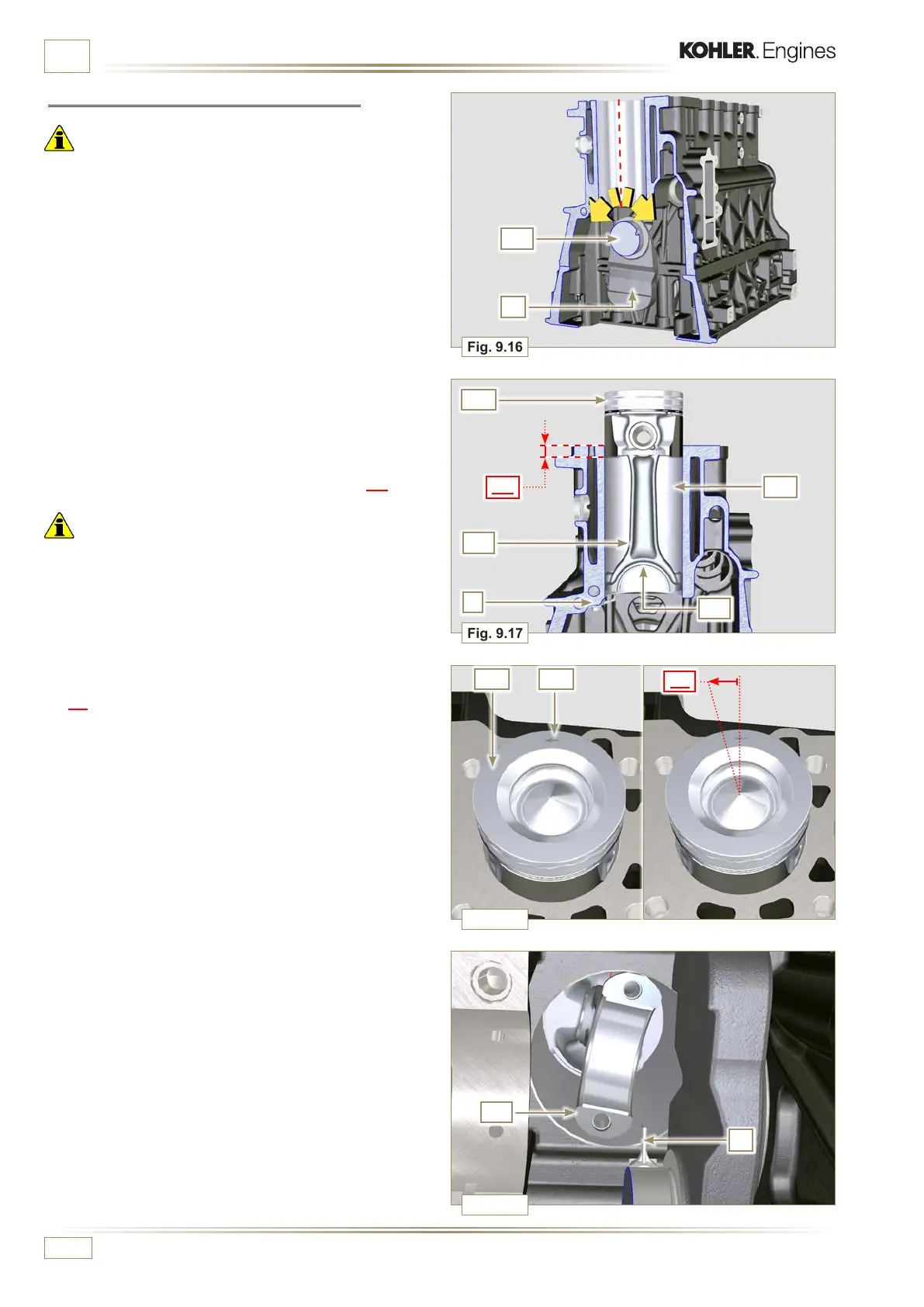
2 - Lubricate the piston skirt and rings AQ.
3 - Check that the half-bearing AS is mounted correctly and
lubricate it thoroughly.
4 - Using the piston ring compression pliers, insert the piston
inside the cylinder BQ by around 10mm (height BM).
Important
• Make sure you are at the stage described in Point 1.
• The piston AQ must be mounted with the arrow BN (stamped
on the piston crown) facing the timing system side.
5 -
Rotate the piston AQ by 10° counter-clockwise with
respect to its correct assembly position (Fig. 9.18 - height
BP).
NOTE: Doing this prevents the impact between the connecting
rod AZ and the sprayer V.
9.3.9 Piston and connecting rod assembly
Important
• Before assembling the piston and connecting rod assemblies,
execute the controls described in Par. 8.5.
1 - Rotate the crankshaft W by moving the crankpin BG to a
TDC position of the affected cylinder.

 Loading...


