9
135
_07
Fig. 9.23
AU
AU
Fig. 9.22
AV
AZ
AU
AS
Fig. 9.21
W
W
AQ
AZ
BG
BG
BR
Fig. 9.20
AQ
ED0053029590
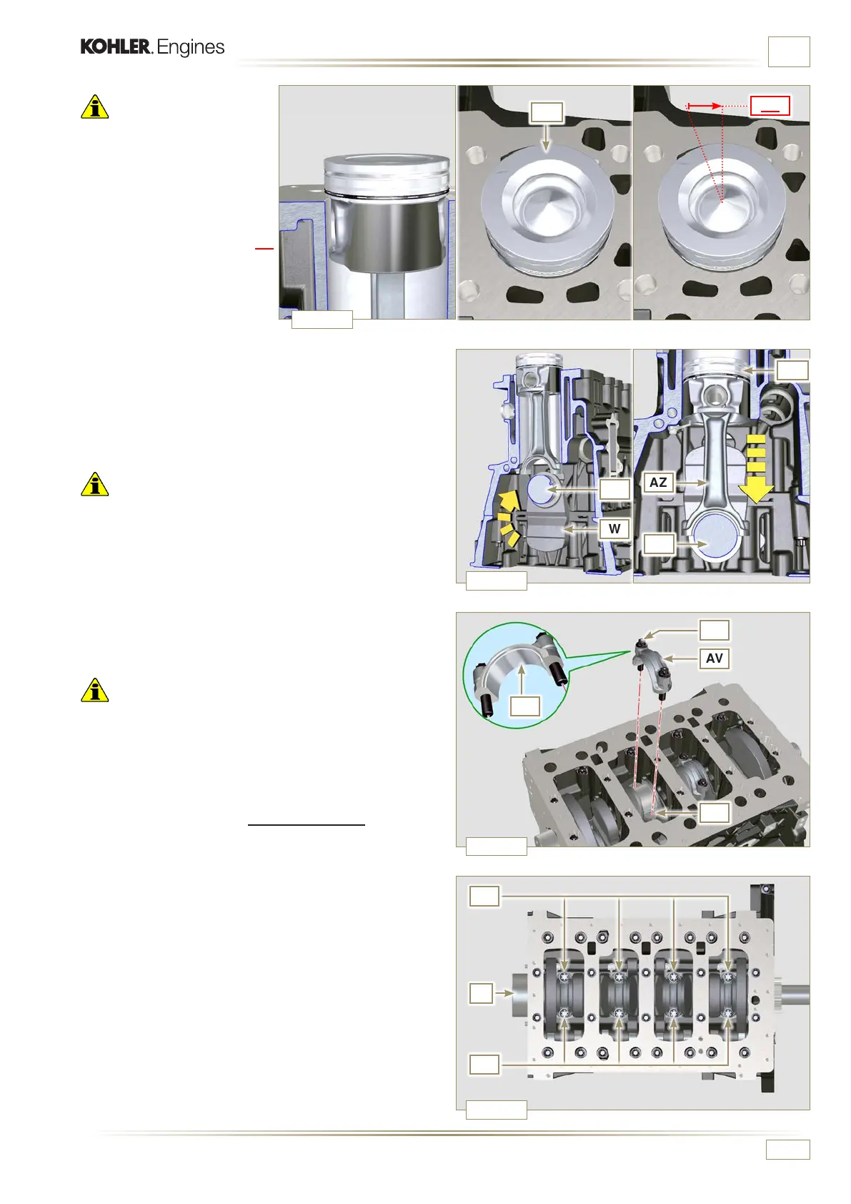
ASSEMBLY INFORMATION
Important
• Leave the ring compressor
assembled on the piston
6 - Push piston AQ downwards
without introducing the
segments in the cylinder,
rotate piston AQ by 10° in a
clockwise direction (value BR
– correct assembly position).
7 - Push the piston AQ downwards by centering the crankpin
BG with the connecting rod AZ.
8 - Turn the crankcase on support to assemble the con rod
capp on cylinder 1 and 4.
9
- Check that the half-bearing AS is mounted correctly on the
connecting rod cap AV.
Important
• Check that the break levels of connecting rod cap AV coincide
perfectly onto connecting rod AZ before screwing on and
tightening capscrews AU.
10 - Couple the connecting rod cap AV to the connecting rod
AZ using the marks made at disassembly (Par. 7.15.2 e
7.15.5).
11 - Screw in the screws AU.
12 - Repeat the operations from 1 to 10 for each cylinder.
Important
• Failure to adhere to the assembly procedures may
compromise the functionality of the engine, and also cause
damage to persons and property.
13
- Tighten the screws AU, alternately, strictly following the
tightening torques indicated.
Tightening sequence of screws Torx M10x1:
1° CYCLE - with a torque of 40 Nm;
2° CYCLE - with a torque of 85 Nm;
14 -
Check that the connecting rods have axial play and the
crankshaft W rotates smoothly.
NOTE:
After the check carried out at point 14, position the
shaft W with the rst cylinder to TDC.

 Loading...


