40
2
_07
1
76
8
4
5
12
3
1110
9
2
Fig. 2.26
4
5
13
14
Fig. 2.27
ED0053029590
TECHNICAL INFORMATION
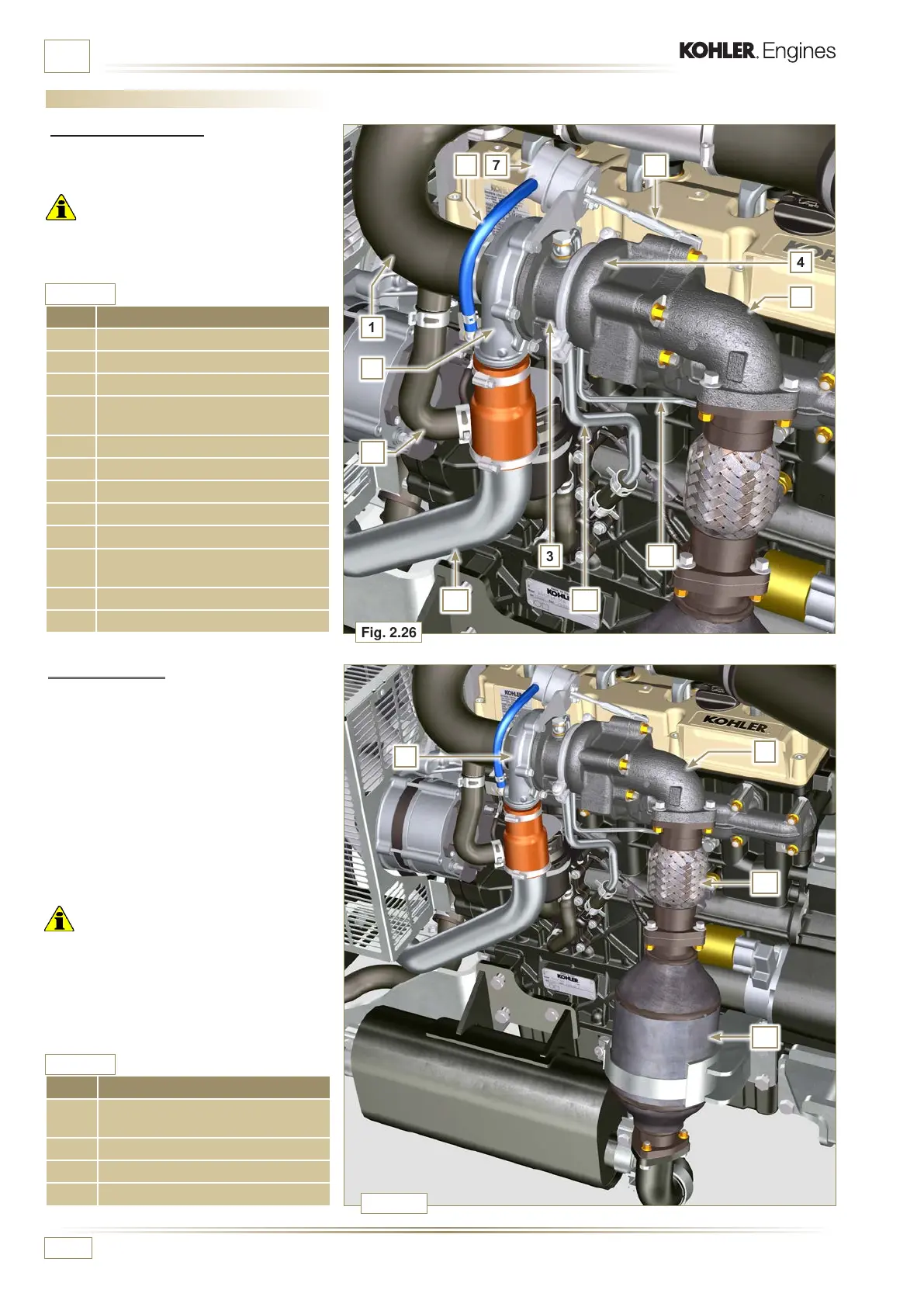
2.12.2 Catalyst
The catalyst is a device to lter exhaust gas
by means of its oxidation.
Internally, it is composed of hundreds of small
ducts that enable the passage of exhaust gas.
It contains precious metals (platinum,
palladium, iridium).
NOTE: The image is indicative only.
The installation of the catalyst must
be approved by KOHLER, for each
application.
Important
• In order to prevent breakage on the
connection ange, the catalyst must be
connected via a exible exhaust tube.
POS. DESCRIPTION
1 Air intake hose
2 Air compression volute
3 Turbo charger central body
4
Turbine housing with Waste Gate
valve
5 Gas exhaust ange
6 Waste Gate control valve hose
7 Waste Gate valve control actuator
8 Waste Gate control valve linkage
9 Engine crankcase breather
10
Air compressed ow pipe to
intercooler
11 Oil drain pipe
12 Turbo charger lubrication pipe
POS. DESCRIPTION
4
Turbine housing with Waste Gate
valve
5 Gas exhaust ange
13 Catalyst
14 Flexible exhaust tube
Tab. 2.29
Tab. 2.30
2.12 Intake and exhaust circuit
2.12.1 Turbocharger
The turbocharger is controlled by means of
exhaust gas that activates the turbine.
Important
• See Par. 2.19.

 Loading...


