39
2
_07
2
13
4
8
6
5
7
1
2
3
Fig. 2.22
Fig. 2.23
1
2
3
4
5
Fig. 2.24
2
2
1
3 4
5
Fig. 2.25
6
7
ED0053029590
TECHNICAL INFORMATION
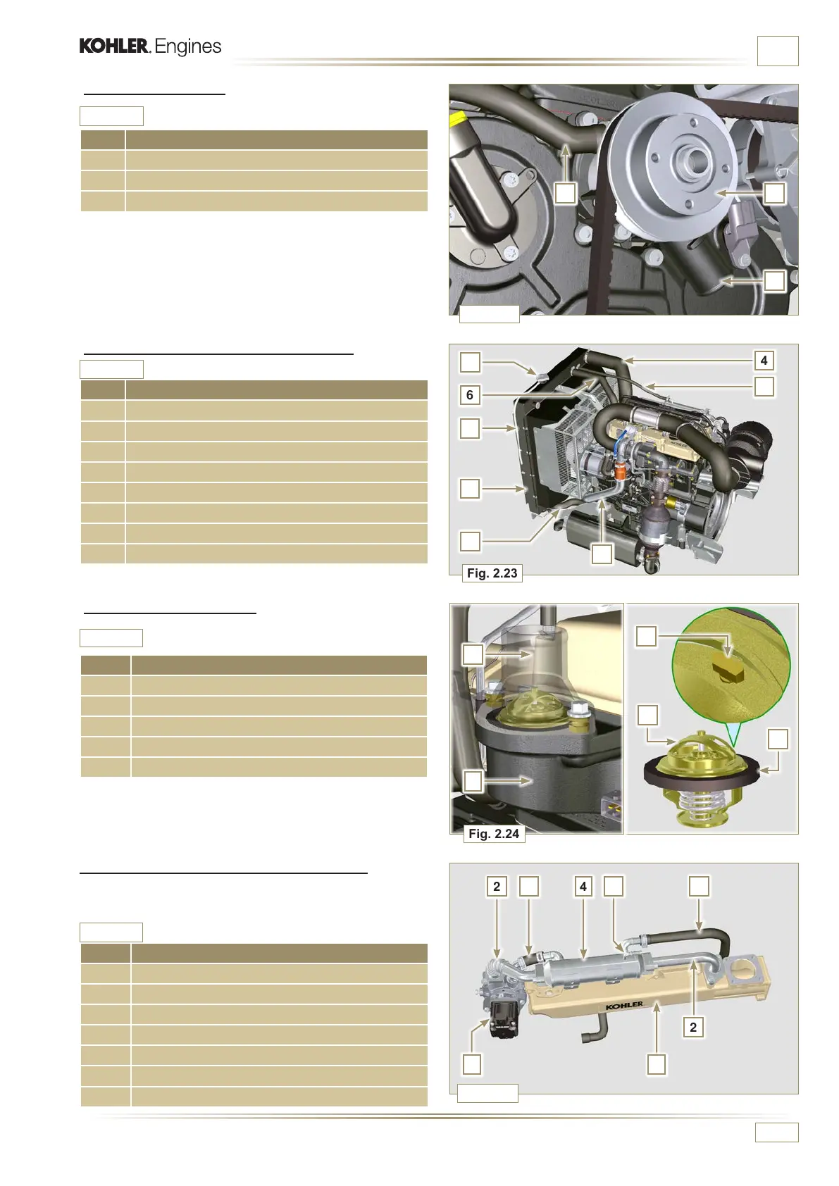
2.11.2 Coolant pump
POS. DESCRIPTION
1 Coolant pump control pulley
2 Coolant intake tting
3 Coolant return hose from the Oil Cooler
2.11.3 Radiator with Intercooler (optional)
POS. DESCRIPTION
1 Radiator with intercooler
2 Coolant rell cap
3 Radiator coolant vent tube or return
4 Air hose (from Intercooler to manifold)
5 Intercooler air delivery hose
6 Coolant ow manifold
7 Coolant intake manifold
8 EGR Cooler coolant vent tube or return
Tab. 2.25
Tab. 2.26
2.11.4 Thermostatic valve
POS. DESCRIPTION
1 Cylinder head
2 Coolant outlet cover
3 Thermostatic valve
4 Gaskets
5 Air bleeding hole
Tab. 2.27
Starting opening temperature of +79° ± 2°C.
2.11.5 EGR gas circuit cooling (EGR Cooler)
Device that cools exhaust gas
Tab. 2.28
POS. DESCRIPTION
1 EGR valve
2 EGR gas passage tubes
3 Coolant outlet hose
4 EGR Cooler
5 Coolant draining union
6 Coolant delivery hose
7 Intake manifold

 Loading...


