6
77
_07
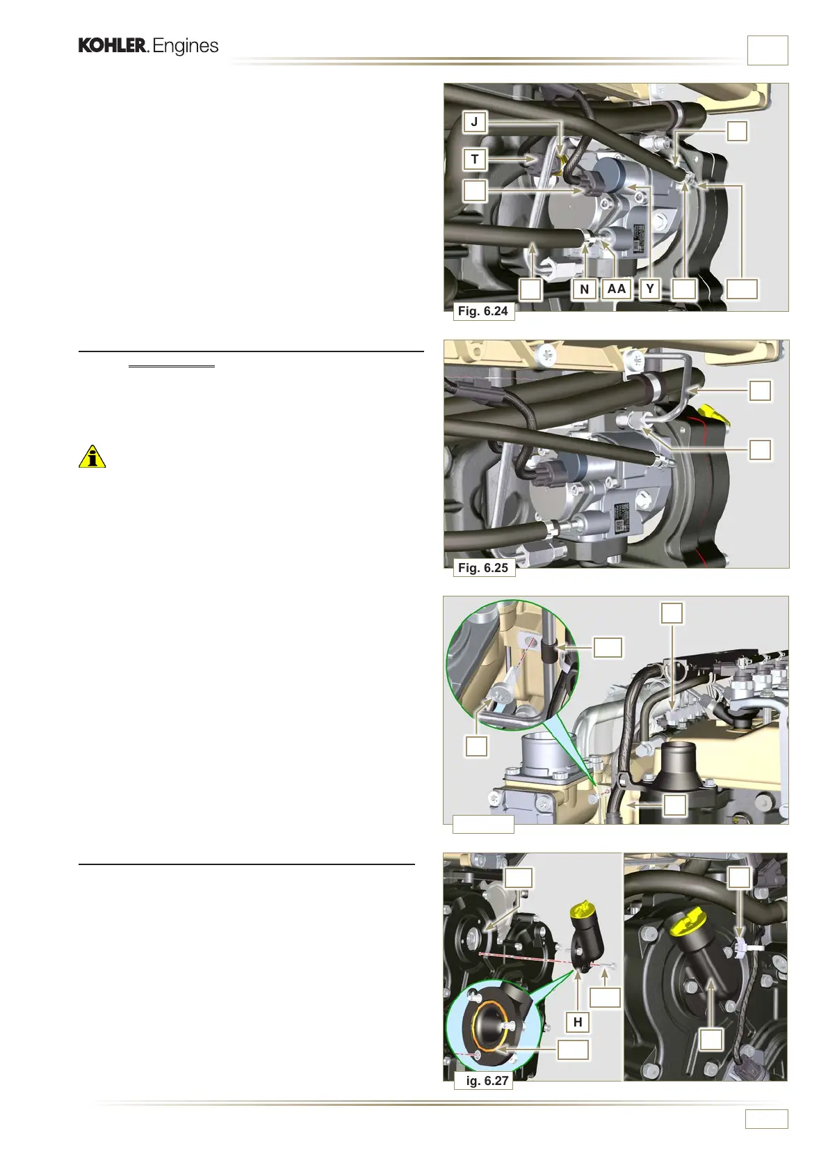
Fig. 6.24
Q
N
AA Y
N
AB
P
Fig. 6.25
F
J
T
S
A
Fig. 6.27
H
AF
AG
AE
E
Fig. 6.26
AC
D
C
B
H
ED0053029590
INFORMATION FOR REPLACING THE FUNCTIONAL UNITS
6.2.5 High-pressure line assembly (injection pump /
Common Rail)
1 - Remove the protection cap.
2 - Position the pipe F.
Important
• Manually tighten the nut A.
7 -
Fit the connector T on the sensor J.
8 -
Fit the connector S on the sensor Y.
9 - Remove the protection caps.
10 - Fit the pipe Q on the fitting AA.
11 - Fit the pipe P on the fitting AB.
12 - Hook the clamps N on the hoses Q and P.
3 -
Manually tighten the nut D.
4 - Fix clamp AC by means of capscrew B on intake manifold
C (tightening torque 10 Nm - ST_06).
5 - Clamp nut D (tightening torque at 30 Nm) and A (tightening
torque at 25 Nm) in sequence.
6.2.6 Timing system carter oil lling ange assembly
NOTE: Always replace the gasket AE after each assembly.
1 - Position the gasket AE in the set on the flange H.
2 - Fix the flange H on the crankcase AF with the screws AG
(tightening torque at 10 Nm - ST_06).
3 - Fit the clamp E on the flange H.
4
- Disassemble the special tool ST_34 and assemble the starter
motor (tightening torque 45 Nm).

 Loading...


