6
76
_07
Fig. 6.20
R
K
Z
V
Fig. 6.21
M
D
C
Fig. 6.23
U
AB
Fig. 6.22
L
Z
W
AH
AA
ED0053029590
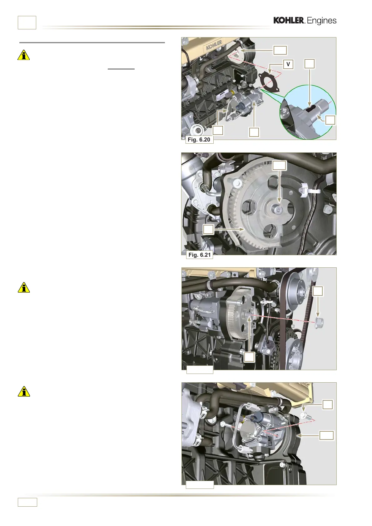
INFORMATION FOR REPLACING THE FUNCTIONAL UNITS
6.2.4 High-pressure fuel injection pump assembly
Important
• Before assembling, carefully read Par. 2 .18.1.
• Always replace the gasket V after each assembly.
The gasket V can only be fitted in one direction.
• Remove the tool ST_04 from the pump control gear (Ref. M
of Par. 6.2.3) if applicable.
• Do NOT use the cylinder connection pipe W as a handle, to
prevent damage or fuel leaks.
• Remove the protection caps only when reconnecting the
hoses.
1 -
Check that the contact surfaces AA are free from
impurities.
2 - Insert the reference key K in the seat of the shaft Z.
3 - Assemble the new gasket V on injection pump R. Insert
injection pump R in its housing on crankcase AA making
key K coincide with key seat AH of gear M.
4 - Fully tighten the nut L on the shaft Z of the injection pump.
Important
• Apply nut L by hand, but do not tighten.
Important
• It is mandatory to replace the screws U or apply a few drops
of Loctite 270.
5 - Clamp the screws U on the crankcase AB (tightening
torque at 25 Nm).
6 - Clamp the nut L (Fig. 6.22) (tightening torque at 70 Nm).

 Loading...


