6
75
_07
Fig. 6.16
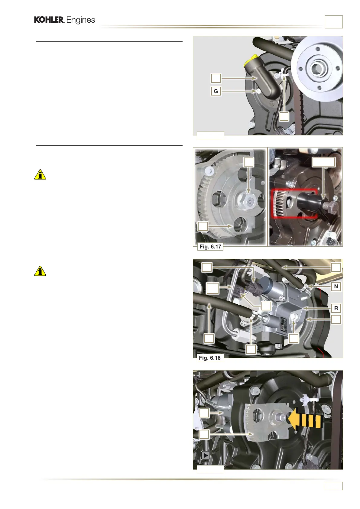
Fig. 6.17
G
E
H
L
ST_04
M
Fig. 6.18
N
R
PS
T
Q
N
U
Fig. 6.19
R
M
W
V
ED0053029590
INFORMATION FOR REPLACING THE FUNCTIONAL UNITS
6.2.2 T i m i n g s y s t e m c a r t e r o i l l l i n g a n g e d i s a s s e m b l y
1 - Remove starter motor (Pa r. 7.3.2) and assemble special
tool ST_34 (Par. 7.7 point 2).
2 - Undo the screws G (ST_06), remove the clamp E and the
flange H.
6.2.3 High-pressure fuel injection pump disassembly
1 - Undo and remove nut L fixing the fuel feeding pump control
gear M.
Important
• Be careful that the nut L does not fall into the timing cover.
2 - Tighten tool ST_04 on the gear M.
Important
• Do NOT use the cylinder connection pipe W as a handle, to
prevent damage or fuel leaks.
• Before disassembling, carefully read Par. 2 .18.1.
• Seal all injection component unions as illustrated in Pa r. 2 . 9 . 8 .
3 - Release the clamps N on the return pipe P and on the fuel
inlet pipe Q.
4 - Disconnect tubes P and Q from fuel feeding pump R.
5 - Disconnect connectors S and T.
6 - Loosen the screws U.
7 - Redo the capscrew of tool ST_04 to disconnect injection
pump R from gear M.
8 - Undo capscrews U and extract injection pump R with the
relevant gasket V.
9 - Undo and remove the tool ST_04.

 Loading...


