SECTION 6
ELECTRICAL SYSTEMS AND
COMPONENTS
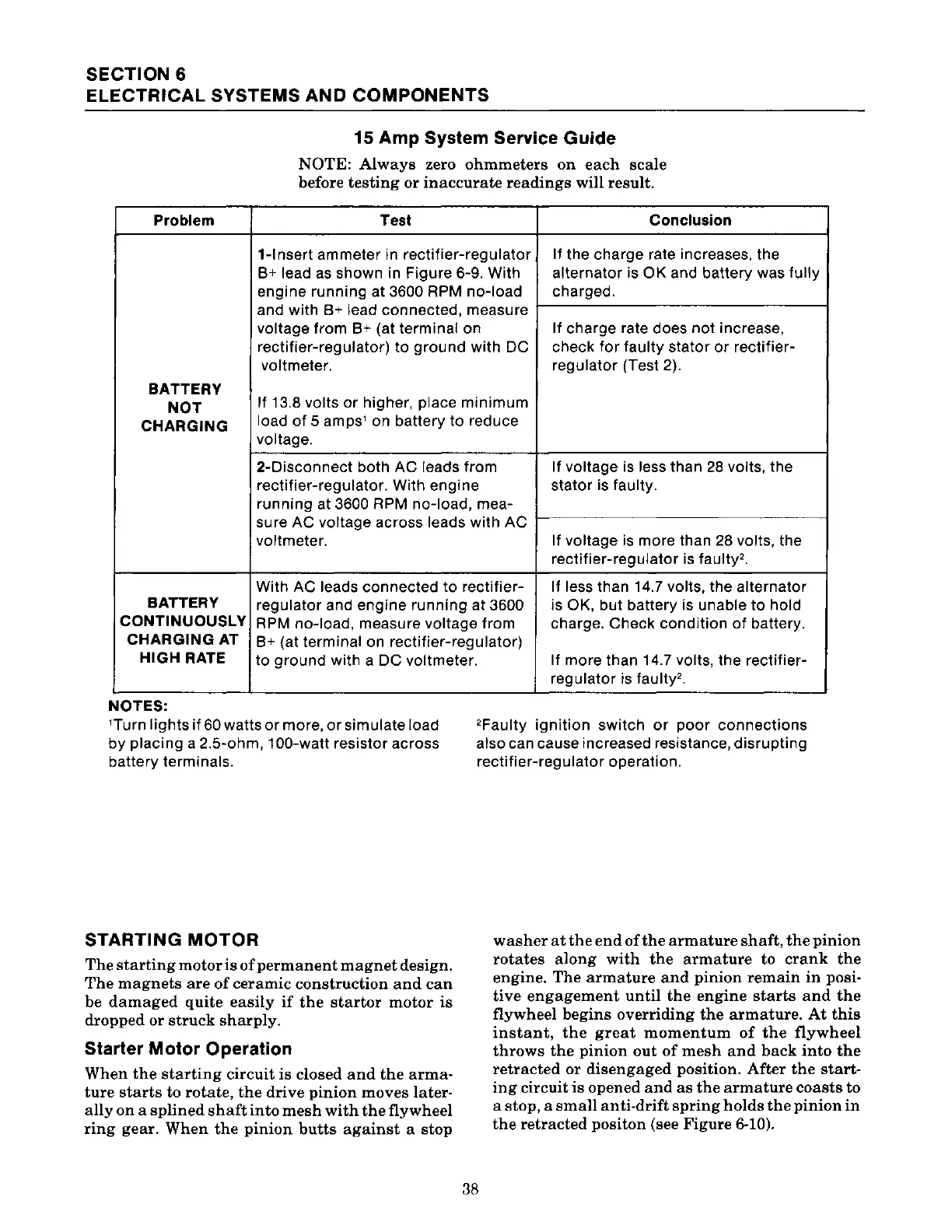
Problem
BATTERY
NOT
CHARGING
BATTERY
CONTINUOUSLY
CHARGING
AT
HIGH RATE
NOTES:
15 Amp System Service Guide
NOTE:
Always
zero
ohmmeters
on
each
scale
before
testing
or
inaccurate
readings
will result.
Test Conclusion
1-lnsert ammeter in rectifier-regulator
If the charge rate increases. the
B+
lead
as
shown in Figure 6-9. With
alternator is
OK and battery was
fully
engine running at 3600 RPM no-load charged.
and with B+ lead connected, measure
voltage from
B+
(at terminal on
If
charge rate does not increase,
rectifier-regulator) to
ground
with DC check
for
faulty stator
or
rectifier-
voltmeter.
regulator (Test 2).
If 13.8 volts
or
higher, place
minimum
load
of
5 amps' on battery
to
reduce
voltage.
2-Disconnect both
AC
leads from
If
voltage is less than
28
volts, the
rectifier-regulator. With engine stator is faulty.
running at 3600 RPM no-load, mea-
sure AC voltage across leads with AC
voltmeter.
If voltage
is
more than
28
volts, the
rectifier-regulator is faulty'.
With
AC leads connected
to
rectifier- If less than 14.7 volts, the alternator
regulator and engine running at 3600 is
OK, but battery is unable
to
hold
RPM
no-load, measure voltage from charge. Check condition
of
battery.
B+
(at terminal on rectifier-regulator)
to
ground
with a DC voltmeter.
If
more than 14.7 volts, the rectifier-
regulator
is
faulty'.
'Turn lights
if
60 watts
or
more,
or
simulate load
by
placing a 2.5-ohm, 100-watt resistor across
battery terminals.
'Faulty
ignition
switch
or
poor
connections
also can cause increased resistance, disrupting
rectifier-regulator operation.
STARTING
MOTOR
The
starting
motor
is
of
permanent
magnet
design.
The
magnets
are
of
ceramic
construction
and
can
be
damaged
quite
easily
if
the
startor
motor
is
dropped
or
struck
sharply.
Starter Motor Operation
When
the
starting
circuit
is
closed
and
the
arma-
ture
starts
to
rotate,
the
drive
pinion
moves
later-
ally
on
a
splined
shaft
into
mesh
with
the
flywheel
ring
gear.
When
the
pinion
butts
against
a
stop
38
washer
at
the
end
of
the
armature
shaft,
the
pinion
rotates
along
with
the
armature
to
crank
the
engine.
The
armature
and
pinion
remain
in
posi-
tive
engagement
until
the
engine
starts
and
the
flywheel
begins
overriding
the
armature.
At
this
instant,
the
great
momentum
of
the
flywheel
throws
the
pinion
out
of
mesh
and
back
into
the
retracted
or
disengaged
position.
After
the
start-
ing
circuit
is
opened
and
as
the
armature
coasts
to
a
stop,
a
small
anti-drift
spring
holds
the
pinion
in
the
retracted
positon
(see
Figure
6-10).
 Loading...