EasyManua.ls Logo

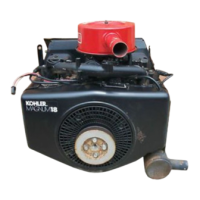
Kohler MAGNUM M18

Kohler MAGNUM M18
139 pages
To Next Page IconTo Next Page
To Previous Page IconTo Previous Page
Loading...
SECTION
9
DISASSEMBLY
DISCONNECT
WIRING;
REMOVE
RECTIFIER-REGULATOR,
KEY
SWITCH,
AND
SOLENOID
1.
Remove
the
connector
from
rectifier-regulator.
Remove
the
lead
from
center
position
of
connec-
tor.
Remove
the
hex.
cap
screws
and
rectifier-
regulator.
Refer
to
Figure
9-9.
fou
Blower
Housing
Hex
Cap
a
Screws
:
Miron
8
Rectifier-Regulator
R
Figure
9-9.
Removing
Rectifler-Regulator.
2.
Remove
the
connector
trom
key
switch.
Remove
kill
lead
from
connector.
Remove
the
self-tapping
screws
and
panel
with
key
switch.
Refer
to
Figure
9-10.
Keyswitch
ue
Panel
Connector
Self-Tapping
Self-Tapping
Screw
||
Screw
Figure
9-10.
Removing
Key
Switch.
3.
Disconnect
the
leads
from
starter
solenoid.
Re-
move
the
wire
tie,
self-tapping
screws,
solenoid
with
bracket,
and
spacer.
Refer
to
Figure
9-11.
9.4
Selt-Tapping
Screw
Solenoid
g
Screw
And
Spacer
Figure
9-11.
Removing
Starter
Solenold.
REMOVE
TOP
BAFFLE,
CYLINDER
HEAD
BAFFLES,
AND
BLOWER
HOUSING
1.
Remove
the
self-tapping
screws
and
top
baffle.
2.
Remove
the
self-tapping
screws
and
#1
side
cyl-
inder
head
baffle.
3.
Remove
the
self-tapping
screws
and
#2
side
cyl-
inder
head
райе.
4.
Remove
the
self-tapping
screws
and
blower
housing.
REMOVE
BREATHER
AND
VALVE
COVER
On
#1
Side
1.
Remove
the
hex.
nut,
copper
washer,
breather
cover,
and
gasket.
Refer
to
Figure
9-12.
Hex
Nut
And
Copper
Washer
Breather
Cover
Hex
Nut
And
Valve
Cover
Copper
Washer
Figure
9-12.
Removing
Breather
and
Valve
Cover.
2.
Remove
the
filter,
seal,
breather
plate,
and
gasket.
Refer
to
Figure
9-13.

Related product manuals