TT-1618 6/14 3
Installation Procedure
The wireless access point hardware must be installed
inside the generator set enclosure. See Figure 5,
Figure 6, or Figure 7 for the recommended location on
your generator set model.
The ambient temperature must be warmer than 0_C
(32_F) at the time of installation. Once installed, the
VHB mounting tape is rated for --35 to 110_C
(--31 to 230_F).
1. Disable the generator set to prevent
accidental starting.
1.1 Press the OFF button on the generator set
controller.
1.2 Disconnect the utility power to the generator set.
1.3 Disconnect the generator set engine starting
battery(ies), negative (--) lead first.
2. Remove enclosure doors and/or panels
as necessary to access the air intake
area or the engine compartment (RCL
models).
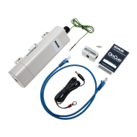
3. Install the wireless access point and
Power over Ethernet (PoE) box.
3.1 See Figure 5, Figure 6, or Figure 7 for the
recommended mounting locations on your
generator set model. Make sure the surfaces
where the PoE box and access point will be
mounted are clean and dry.
3.2 Cut one piece of VHB tape approximately 1 inch
long. Use the tape to attach the Power over
Ethernet (PoE) box GM91273-3 inside the
enclosure as shown for your model in Figure 5,
Figure 6, or Figure 7.
3.3 Cut two or three pieces of the VHB tape
GM91273-5 (provided in the kit) approximately
2.5 inches long. Use the VHB tape to attach
wireless access point GM91273-1 to the inside
of the enclosure as shown for your model in
Figure 5, Figure 6, or Figure 7.
3.4 Connect cable 357477 to the port on the bottom
of the wireless access point. Connect the other
end of the cable to the PoE port on the PoE box.
SeeFigure2.
3.5 Connect the power cable to the DC port on the
PoE box. See Figure 2.
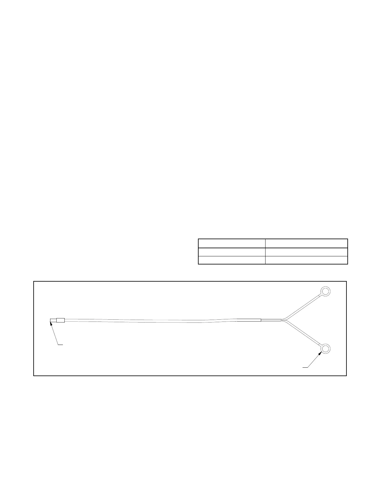
3.6 Connect the ring terminals on the power cable to
the generator set battery terminals. Follow the
polarity in Figure 3. See Figure 4 for an
illustration of the power cable.
Cable Battery Terminal
Black Positive (+)
Black and White Negative (--)
Figure 3 Power Cable Battery Connections
1
GM91273
1. Connect to PoE box DC port
2. Connect ring terminals to generator set battery
2
NOT TO SCALE
Figure 4 Power Cord