EasyManua.ls Logo

Kohler OnCue Plus Wireless Kit User Manual

Kohler OnCue Plus Wireless Kit
16 pages
To Next Page IconTo Next Page
Page #1 background imageLoading...
Page #1 background image
TT-1618 6/14
INSTALLATION INSTRUCTIONS
Original Issue Date: 6/14
Model: 6--60 kW Generator Sets with RDC2/DC2, VSC, or RDC/DC Controller
Market: Residential/Light Commercial
Subject:
OnCuer Plus Wireless Kits GM62465-KP3-QS and GM81385-KP3-QS
Introduction
The OnCuer Plus Wireless Kit allows wireless
connection of residential/light commercial generator
sets to the owner’s wireless router for Internet access.
Use this kit to connect the generator set to the Internet
for the Kohlerr OnCuer Plus Generator Management
System.
The kit uses a wireless access point (AP) to connect the
generator set to the Internet without running a cable
from the owner’s router to the generator set. The
wireless AP is installed inside the generator enclosure
and powered by the generator’s engine starting battery.
These instructions explain installation and setup of the
wireless AP.
The VHB tape provided with the kit allows installation of
the kit components without drilling additional holes or
using special tools. The ambient temperature must be
warmer than 0_C(32_F) at the time of installation. Once
installed, the tape is rated for --35 to 110_C
(--31 to 230_F).
See Figure 1 to identify the correct OnCue Plus wireless
kit for your generator model. See Figure 2 for the
wireless access point (tape not shown).
Special Equ ipment
The following items are required for installation and
setup.
D Wireless router for Internet connection, customer-
provided
D The customer’s wireless network security properties
and password are required. Step 11 of these
instructions explains how to obtain this information.
D Laptop computer (for initial setup only)
D Network cable for temporary connection of laptop PC
to the kit (for initial setup only)
Generator Model Wireless Kit Number
14/20RES GM62465-KP3-QS
6VSG
14/20RESA
38/48/60RCL
GM81385-KP3-QS
Figure 1 Kits and Models
5
tt1618
1. Wireless access point GM91273-1
2. Cable 357477
3. LAN port
4. Power over Ethernet (PoE) box GM91273-3
5. Power cable provided with kit (see Figure 4)
6. PoE port
Note: VHB mounting tape is not shown in this photo.
41
2
6
SeeFigure4.
3
Figure 2 GM91273 Wireless Access Point
Assembly
Question and Answer IconNeed help?

Do you have a question about the Kohler OnCue Plus Wireless Kit and is the answer not in the manual?

Kohler OnCue Plus Wireless Kit Specifications

General IconGeneral
BrandKohler
ModelOnCue Plus Wireless Kit
CategoryAdapter
LanguageEnglish

Summary

Generator Safety Precautions

Generator Safety: Accidental Start & Disabling

Precautions for accidental starting and disabling the generator set to prevent injury.

FCC Compliance and Radiation Safety

Details FCC compliance, interference, and radiation exposure guidelines for the device.

Wireless AP Installation Procedure

Disable Generator and Prepare for Install

Steps to disable the generator and remove panels for accessing the enclosure.

Mount AP and PoE Box with VHB Tape

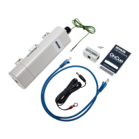
Instructions for mounting the wireless access point and PoE box using VHB tape.

Connect Cables and Power to Generator

Connects the wireless access point, PoE box, and generator battery terminals.

Wireless Access Point Setup Guide

Connect Laptop and Configure PC IP Address

Connect laptop to access point and set PC's IP address for Windows setup.

Configure Mac IP and Gateway Settings

Steps for Mac users to configure IP address and gateway for connection.

Access and Configure AP Wireless Settings

Sign in and configure the wireless access point's network mode and wireless client settings.

Connect to Customer's Wireless Network

Select and connect to the customer's wireless network, including security settings.

Test Connectivity and Disconnect Laptop

Test internet connection and disconnect the laptop from the access point.

Return Generator to Service

Reconnect battery, replace panels, and start the generator.

Wireless AP Troubleshooting and Watchdog

Configure Watchdog for Connection Monitoring

Configuring the watchdog feature to monitor connection and enable automatic resets.

Confirm Watchdog and Adjust IP Address

Verify watchdog operation and procedures for changing the IP address if necessary.

Additional Device Information

LED Indicator Status Meanings

Explains the meaning of different LED states for power, LAN, and WLAN indicators.

Internal Antenna Electrical Specifications

Provides technical specifications for the internal antenna, including gain and frequency.