Bucket 1.5 t/m
3
m
3
/ kg
1.38 / 1025 1.25 / 950
Bucket 1.8 t/m
3
m
3
/ kg
1.20 / 925 1.09 / 875
Values shown are in accordance with EN474-5:2006+A1:2009 (E)
TOOL CONTROL SYSTEM WITH ADDITIONAL MONITOR (IF EQUIPPED)
SYSTEM OVERVIEW
The machine may be equipped with a tool control system, the system limits 1st attachment line flow and pres-
sure and 2nd attachment line flow.
The system can store settings for up to 16 different attachments, to adjust attachment settings please contact
your Komatsu distributor.
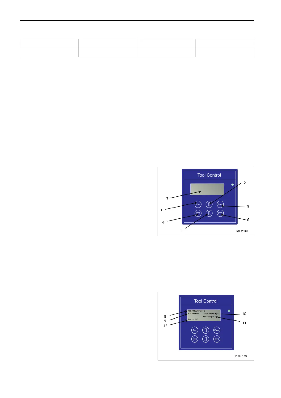
The tool control system monitor is located in the operator cab on the door pillar.
(1) Esc button (return/cancel)
(2) Navigation button up
(3) Enter button
(4) Navigation button left
(5) Navigation button down
(6) Navigation button right
(7) Monitor display screen
SYSTEM OPERATION
The system is automatically activated when the ignition key is turned to ON position. On startup the tool control
system monitor screen displays the following information:
(8) Current selected tool (at last key off)
(9) Pre-set 1st Attachment line pressure limit (Bar)
(10) Pre-set 1st Attachment line flow rate (l/min)
(11) Pre-set 2nd Attachment line flow rate (l/min)
(12) Monitor status
ATTACHMENTS AND OPTIONS ATTACHMENTS AND OPTIONS
6-60
 Loading...