Do you have a question about the Komatsu PC450-8 and is the answer not in the manual?
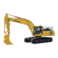
Details of the hydraulic excavator model and serial number information.
Lists the serial number ranges for different models of the hydraulic excavator.
Explains the manual's purpose and stresses the importance of reading safety precautions.
Specifies the designated location for the operation and maintenance manual within the cab.
Defines signal words (Danger, Warning, Caution) and their hazard level implications.
Explains the use of safety labels with words and pictograms for hazard communication.
Details the sound pressure and sound power levels emitted by the machine.
Provides information on vibration levels transmitted to the operator and methods to reduce them.
Lists the primary work applications for the Komatsu machine.
Defines terms like front, rear, left, and right relative to the operator's seat.
Details proximity and 12m circumference visibility areas, noting blind spots.
Provides instructions and precautions for the initial 100-hour break-in period.
Location and description of the machine's identification and serial number plates.
Information on EPA regulations and the location of the engine number plate.
Identifies the location of the service meter on the machine monitor.
Provides fields for entering machine and distributor serial numbers and contact details.
Details the information found on the machine serial plate.
General safety rules for machine operation and maintenance, including personnel qualifications.
Provides location and understanding of safety labels affixed to the machine.
Guidance on appropriate attire and personal protective equipment for safe operation.
Information on the provision and use of fire extinguishers and first aid kits.
Procedure for safely leaving the operator's seat, including securing the machine.
Safety instructions for mounting and dismounting the machine using handrails and steps.
Precautions to prevent burns from hot coolant and oil.
Measures to prevent fire and explosion caused by fuel, oil, and electrical systems.
Measures to protect the operator's cab from falling or flying objects.
Precautions for safe operation at various jobsite conditions, including combustible materials and utilities.
Guidelines for maintaining safe distances from electric cables to prevent electric shock.
Tips for ensuring good visibility, including mirror checks and use of flagmen.
Importance of ventilation to prevent gas poisoning from exhaust fumes.
Precautions regarding asbestos dust exposure during demolition or waste handling work.
Procedures and checks required before starting the engine.
Daily checks to ensure the machine is safe for operation.
Guidelines for safely changing the machine's direction of travel.
Precautions for safe travel on level ground, rough ground, and slopes.
Specific procedures for safe travel on slopes to prevent tipping or slipping.
Lists operations that should be avoided to ensure machine longevity and safety.
Precautions for operating the machine on snow-covered or frozen surfaces.
Instructions for safely parking the machine on level ground or slopes.
Procedures for transporting the machine, including loading and unloading.
Safety guidelines for handling and charging the battery to prevent explosions.
Detailed instructions for safely connecting and using booster cables.
Essential safety rules for towing a disabled machine correctly.
Guidelines for safely lifting objects using the bucket.
General safety information related to performing maintenance tasks.
Diagram identifying major components of the hydraulic excavator.
Diagram and list of all controls and gauges in the operator's cabin.
Explanation of different display screens (standard, all lamps, maintenance warning).
Details on monitoring system components: emergency, caution, and basic check monitors.
Step-by-step guide to the machine monitor's basic operation when starting the engine.
Describes the screen display when stopping the engine under normal conditions.
Explains monitor changes when abnormalities occur during engine starting.
Describes monitor changes when abnormalities occur during machine operation.
Table detailing monitor light colors for normal, abnormal, and low temperature conditions.
Details on emergency monitors like coolant and oil pressure, and their indications.
Explanation of caution monitors that warn of potential issues requiring immediate action.
Monitors for basic checks before starting, emphasizing direct inspection over reliance on monitors.
Explanation of pilot display and gauge/meter functions for pre-heating and travel speed.
Description and operation of monitor switches for working mode and air conditioning.
Guide on operating function switches, including camera screen selection.
Procedure to follow when an error or alarm occurs during camera display.
How to switch between service meter and clock displays on the monitor.
Instructions for accessing and resetting maintenance items on the monitor screen.
Guide to accessing and operating the user menu for machine settings.
Adjusting oil flow for breaker/attachment in B and ATT modes.
Procedure for setting the working mode to 'B' for breaker operations.
Procedure to set the working mode for attachments.
Operation of the 2nd attachment circuit, like clamshell rotation.
Information on the additional filter for hydraulic oil when using a breaker.
Details on hydraulic circuit switching and safety valve pressure settings for attachments.
Instructions for connecting hydraulic circuits when attaching new equipment.
Diagram showing the direction of pedal operation and oil flow path.
Procedure for replacing the additional filter element for the hydraulic breaker.
Step-by-step guide for removing and installing attachments safely.
Instructions for operating attachments, including breaker and crusher controls.
Guide to selecting working modes (P, E, L, B, ATT) for different attachment operations.
How to operate general attachments using rolling switch or control pedal.
Instructions for operating attachment 2, such as clamshell or crusher rotation.
Precautions for storing attachments when not in use for extended periods.
General precautions and advice regarding the use of attachments and options.
Guidance on combining work equipment and attachments, warning of potential interference.
Lists attachment combinations with different arm lengths for PC400 and PC400LC models.
Method for selecting appropriate track shoes based on operating conditions and categories.
Instructions for work using attachments, focusing on hydraulic breaker applications.
Lists operations to avoid for machine longevity and safe work practices.
Basic precautions and warnings related to the KOMTRAX machine management system.
Operation instructions, specifications, and working modes for the super long front attachment.
Detailed explanation of safety lock levers, travel levers, and work equipment control levers.
Instructions for installing supporting links for transport and storage of the super long front.
This section describes operation and maintenance specific to the High Reach Demolition machine.
Diagram identifying major components of the High Reach Demolition machine.
Specific caution items for operating the High Reach Demolition machine.
Illustrates the locations where safety labels should be affixed to the machine.
Details safety labels specific to the Medium Reach Configuration (boom 2 removed).
Explanation of control levers and switches for the High Reach Demolition Equipment.
Instructions for operating travel levers and pedals, including warnings for High Reach Equipment.
Operation of left and right work equipment control levers and pedals for High Reach Equipment.
Details on controlling attachments like the intermediate link and crusher.
Procedure for raising work equipment like boom and intermediate link cylinders.
Defines the safe working ranges and boom angles for the High Reach Demolition machine.
Warns against operating outside the specified working range to prevent machine overturn.
Advises against operating cylinders to their stroke end to prevent damage.
States that the machine is not suitable for breaker use and warns against installing it.
Precautions for medium reach configuration with boom 2 removed.
Procedure for adjusting the hydraulic variable gauge undercarriage (if fitted).
Guide to operating work equipment using control levers and pedals.
Procedures for installing and removing demolition digging booms and related equipment.
Steps for purging air from hydraulic cylinder lines and PPC circuits.
Procedure for loading the machine with high reach demolition equipment onto a trailer.
Procedure for loading the machine with demolition digging equipment onto a trailer.
Procedure for loading the High Reach Demolition Equipment alone onto a trailer.
Steps for preparing High Reach Work Equipment for safe transportation.
Working range specifications for PC450LCD High Reach configuration.
Working range specifications for PC450LCD Medium Reach configuration.
Working range specifications for PC450LCD Low Reach configuration.
Working range specifications for PC450LCD Digging configuration.
Provides weights and dimensions for different configurations of High Reach Demolition Equipment.
Explains the lifting capacity chart for the PC450LCD Super Long Front attachment.
Importance of checking the service meter daily for maintenance scheduling.
Recommendation to use only Komatsu genuine parts for replacements.
Guidance on using Komatsu genuine lubricants and specified oil viscosity.
Instructions for using and handling windshield washer fluid.
Emphasis on using clean oil and grease and maintaining container cleanliness.
Procedure for checking drained oil and filters for metal particles.
Caution regarding the fuel strainer during fueling operations.
Safety precautions and procedures for performing welding on the machine.
Warning about dropping items inside the machine during inspection.
Guidelines on using Komatsu genuine parts, oils, and avoiding mixing different types.
Detailed guidance on handling fluids and the importance of preventing impurities.
Precautions for preventing moisture in the fuel tank and proper fuel usage.
Information on coolant functions, types, and mixing ratios for freezing and corrosion prevention.
Guidance on grease usage for preventing seizure and noises at joints under heavy-duty conditions.
Explanation of the KOWA service for early detection of machine wear and potential failures.
Details on oil sampling intervals and precautions to ensure accurate analysis.
Guidelines for safely storing oil and fuel to maintain quality and prevent contamination.
Importance of filters and procedures for periodic replacement, using genuine parts.
Specific maintenance tasks required after the first 1000 hours of operation.
Tasks to be performed as needed, such as air cleaner element service.
Essential checks to perform before starting the engine each day.
Lubrication and checks required every 50 hours of operation.
Tasks to be performed every 250 hours, including lubricating the swing circle.
Maintenance procedures required every 500 hours, including lubrication and filter replacement.
Procedures for 1000-hour service intervals, including fuel filter replacement.
Maintenance tasks to be performed every 2000 hours, such as changing final drive oil.
Procedures for 4000-hour service intervals, including checking water pump and starting motor.
Maintenance tasks required every 5000 hours, such as changing hydraulic tank oil.
Procedures for 8000-hour service intervals, including replacing high-pressure piping clamps.
Specific maintenance intervals for hydraulic breaker operations.
Procedure for checking and adjusting engine valve clearance, requires special tools.
Steps for checking, cleaning, and replacing the air cleaner element.
Procedure for cleaning the inside of the cooling system and changing coolant.
Procedure for checking and tightening track shoe bolts to prevent breakage.
Steps for checking and adjusting track tension for optimal performance.
Instructions for replacing bucket teeth using vertical pin type.
Instructions for replacing bucket teeth using horizontal pin type.
Procedure for replacing bucket side cutters and shrouds.
Steps for adjusting bucket clearance to ensure proper fit and operation.
Procedure for checking and refilling the window washer fluid.
Inspection and maintenance of the air conditioner system, including refrigerant check.
Procedure for cleaning the washable floor mat inside the cab.
Detailed steps for bleeding air from the hydraulic system, including pump, cylinders, motor, and travel motor.
Summary of essential checks before starting the engine daily.
Lubrication points and procedures for 50-hour service intervals.
Procedure for lubricating the swing circle every 250 hours.
Procedure for checking battery electrolyte levels and safety precautions.
Procedure for checking and adjusting fan and alternator belt tension.
Procedure for checking and adjusting air conditioner compressor belt tension.
Lubrication points and procedures for 500-hour service intervals.
Instructions for replacing the fuel pre-filter cartridge, emphasizing genuine parts.
Procedure for changing engine oil and replacing the oil filter cartridge.
Procedure for cleaning and inspecting heat exchange fins to prevent leakage and overheating.
Steps for cleaning the air conditioner's fresh and recirculated air filters.
Procedure for replacing the breather element in the hydraulic tank.
Procedure for checking and adding oil to the swing machinery case.
Procedure for checking and adding oil to the final drive case.
Procedure for replacing the hydraulic oil filter element.
Procedure for changing the oil in the swing machinery case.
Procedure for checking and adding oil to the damper case.
Instruction to consult Komatsu distributor for checking exhaust pipe clamp tightening.
Procedure for replacing the additional breather element in the hydraulic tank.
Procedure for replacing the corrosion resistor cartridge.
Procedure for changing oil in the final drive case.
Procedure for cleaning the hydraulic tank strainer.
Instruction to consult Komatsu distributor for checking accumulator nitrogen gas charge pressure.
Explains the function of the accumulator in the control circuit.
Procedure for checking the accumulator's function, including nitrogen gas charge pressure.
Procedure for safely releasing pressure in the hydraulic circuit.
Instruction to consult Komatsu distributor for alternator inspection and maintenance.
Instruction to consult Komatsu distributor for engine valve clearance check and adjustment.
Instruction to consult Komatsu distributor for checking vibration damper rubber condition.
Instruction to consult Komatsu distributor for water pump inspection, overhaul, or replacement.
Instruction to consult Komatsu distributor for starting motor check.
Recommendation to replace the accumulator every 2 years or 4000 hours.
Check for loose bolts or hardened rubber parts on piping clamps and consult distributor if issues found.
Check for missing caps/covers or hardened rubber and consult distributor for repairs.
Procedure for changing oil in the hydraulic tank, including warnings and refill capacity.
Procedure for checking and adding oil to the swing machinery case.
Procedure for checking and adding oil to the final drive case.
Procedure for replacing the fuel main filter cartridge, emphasizing genuine parts.
Procedure for replacing the hydraulic oil filter element.
Procedure for cleaning the hydraulic tank strainer.
Instruction to consult Komatsu distributor for checking accumulator nitrogen gas charge pressure.
Table of operating weights, dimensions, and engine specifications for various models.
Specifications for working ranges (digging reach, depth, height) with different arm lengths.
Lifting capacity and working range details for the 6.7m boom configuration.
Lifting capacity and working range details for the 7.0m boom configuration.
Working range specifications for PC450LCD High Reach demolition equipment.
Working range specifications for PC450LCD Medium Reach demolition equipment.
Working range specifications for PC450LCD Low Reach demolition equipment.
Working range specifications for PC450LCD Digging configuration.
Provides weights and dimensions for transport and components of High Reach Demolition Equipment.
Dimensions and weights for transporting High Reach and Medium Reach work equipment.
Dimensions and weights for transporting Digging Equipment (PC450LCD).
Guidance on interpreting the lifting capacity chart for Super Long Front attachment.
General safety advice for installing and using attachments or options on the machine.
Guidance on consulting Komatsu distributor before selecting attachments or options.
Emphasizes reading and understanding manuals for attachments and options before use.
Safety precautions for removing or installing attachments, including using cranes and supports.
Safety advice for operating the machine with long or heavy work equipment installed.
Instructions and warnings for operating hydraulic quick couplers.
Information on hook condition and prohibited operations when using buckets with hooks.
Details on machine locations for attachment controls, stop valve, and selector valve.
Instructions for operating attachment control pedals, with warnings about accidental operation.
Explanation of lock pin positions for controlling attachment pedals and switches.
Information on the additional filter for hydraulic oil when using a breaker.
Explains the accumulator's role in reducing peak hydraulic pressure when using a breaker.
Guide to switching hydraulic circuits based on attachment type and working mode.
Instructions for adjusting oil flow in the service circuit based on attachment type.
Details on switching hydraulic circuits for breaker vs. crusher/general attachments.
Procedure for connecting hydraulic circuits when installing an attachment.
Procedure for replacing the additional filter element for the hydraulic breaker.
Step-by-step guide for removing and installing attachments safely.
Procedure for installing an attachment, including hydraulic circuit purging.
Instructions for operating attachments, including breaker and crusher controls.
Guide to selecting working modes (P, E, L, B, ATT) for different attachment operations.
| Brand | Komatsu |
|---|---|
| Model | PC450-8 |
| Category | Excavators |
| Language | English |