This document is a Field Assembly Instruction manual for the KOMATSU WA470-7 Wheel Loader. It provides detailed procedures for setting up and adjusting various electronic and mechanical systems of the machine after assembly.
Function Description
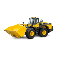
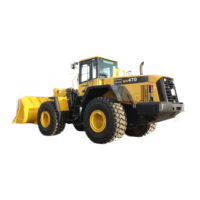
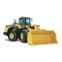
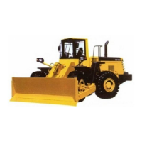
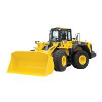
The Komatsu WA470-7 Wheel Loader is a heavy-duty construction machine designed for loading and transporting materials such as sand, gravel, and earth. This manual focuses on the post-assembly adjustments required to ensure the machine operates correctly and safely. The primary functions covered in this manual relate to the electronic control systems that govern the machine's monitor display, work equipment, and rear-view monitoring.
Important Technical Specifications
While the manual doesn't list all technical specifications of the WA470-7, it provides critical parameters and ranges for various adjustments:
- Serial Numbers: The instructions apply to machines with serial numbers 10001 and up.
- Boom Angle Sensor for EPC (Raise):
- Standard (STD) specification: 3.77 ± 0.3 V
- Hi Lift specification: 3.88 ± 0.3 V
- Boom Angle Sensor for EPC (Lower):
- Standard (STD) specification: 1.38 ± 0.3 V
- Hi Lift specification: 1.49 ± 0.3 V
- Tire Size Compensation: Adjustable in 1% increments.
- Work Equipment Control Types: The machine supports various work equipment control types (Type A, B, C, D, E, F, G), each with different main valve and lever configurations (e.g., 2-spool valve, 3-spool valve, MF lever, MF lever and PCS).
- Rear View Monitor Guide Line Position: Adjustable using four points (Point 1, Point 2, Point 3, Point 4) with horizontal and vertical adjustments. The reference distance for placing marks is 1.5 m from the rear end of the machine.
Usage Features
The WA470-7 incorporates several user-adjustable features accessible through the machine's monitor and control switches:
- Machine Monitor Settings: The operator can access a "Service Menu" to configure various settings. This menu includes options for "Monitoring / Pre-defined," "Monitoring / Custom," "Abnormality Record," "Maintenance Record," "Maintenance Mode Setting," "Phone Number Entry," and "Default."
- Abnormality Record Deletion: The system stores electrical system abnormality records, which can be viewed and deleted. Records include chronological order, abnormality type (currently occurring or not), unified failure code (6 digits), failure code, number of occurrences, service meter reading at first occurrence, and service meter reading at last occurrence. Individual records or all records can be deleted.
- Option Selection: Various machine options can be selected and configured through the "Option Select" menu. These options include "Work Equipment Control," "Multicoupler," "Semi-auto Digging," "Load Meter," "Boom Specification," "Auto Grease," "Battery Electrolyte Level Sensor," "Tire Size Compensation," "Emergency Steering," "J/S or FNR Switch," "Lift Up Mode," "E.C.S.," "Torque Converter Lockup," "4th Gear Prohibition," "Two Stage Low Idle," "F1 PWR CUT," and "Komatsu SmartLoader Logic." Each option has specific settings (e.g., ADD, NO ADD, Standard, Hi Lift, Type A, 0%).
- Work Equipment Controller Boom Angle Adjustment: This feature allows for the calibration of the boom angle sensor for both raising and lowering movements. The adjustment involves setting the boom to its upper or lower limit (cylinder stroke end) and pressing the ENTER switch. The system displays "1" for successful adjustment and "2" if the adjustment is out of specification.
- Work Equipment EPC Lever Detent Position Adjustment: This allows for the calibration of the detent positions for boom raise, boom lower (float), and bucket tilt. The process involves moving the lever to the detent position, pressing ENTER, and verifying the setting.
- Work Equipment EPC Starting Current Adjustment: This feature calibrates the starting current for boom raise, boom lower, bucket tilt, and bucket dump functions. The adjustment involves setting the lever to the desired position, pressing ENTER, and verifying the setting.
- Bucket Positioner Setting: The bucket positioner can be set to automatically stop the bucket at a predefined flat level. This involves selecting "Bucket Flat Level Select" from the "Machine Setting / Information" screen and recording three flat levels (A, B, C). The process requires setting the bucket flat on the ground and pressing ENTER.
- Rear View Monitor Guide Line Adjustment: The rear-view monitor's guide lines can be adjusted to match physical marks placed 1.5 m behind the machine. This involves adjusting four points (Point 1, Point 2, Point 3, Point 4) using a luminance control switch for horizontal and vertical alignment.
Maintenance Features
The manual highlights several features that contribute to the machine's maintenance and diagnostic capabilities:
- Abnormality Record: The machine records electrical system abnormalities, providing valuable diagnostic information for troubleshooting. This allows technicians to identify and address issues efficiently.
- Setting of Machine Monitor: The ability to access and configure various settings through the service menu aids in initial setup and ongoing maintenance.
- Calibration Procedures: The detailed calibration procedures for boom angle, EPC lever detent positions, and EPC starting current ensure that the work equipment operates within specified parameters, preventing premature wear and optimizing performance.
- Bucket Positioner: The bucket positioner, once set, can help reduce operator fatigue and ensure consistent bucket operations, which can contribute to longer component life.
- Rear View Monitor Adjustment: Proper calibration of the rear-view monitor guide lines enhances safety during operation, potentially preventing accidents and damage to the machine or surroundings.
The manual emphasizes the importance of following these procedures to ensure the WA470-7 Wheel Loader operates efficiently, safely, and to its full potential. It also includes sections for "Precautions," "Tools to be used," and "Facilities to be used" for each procedure, indicating a comprehensive approach to assembly and maintenance.