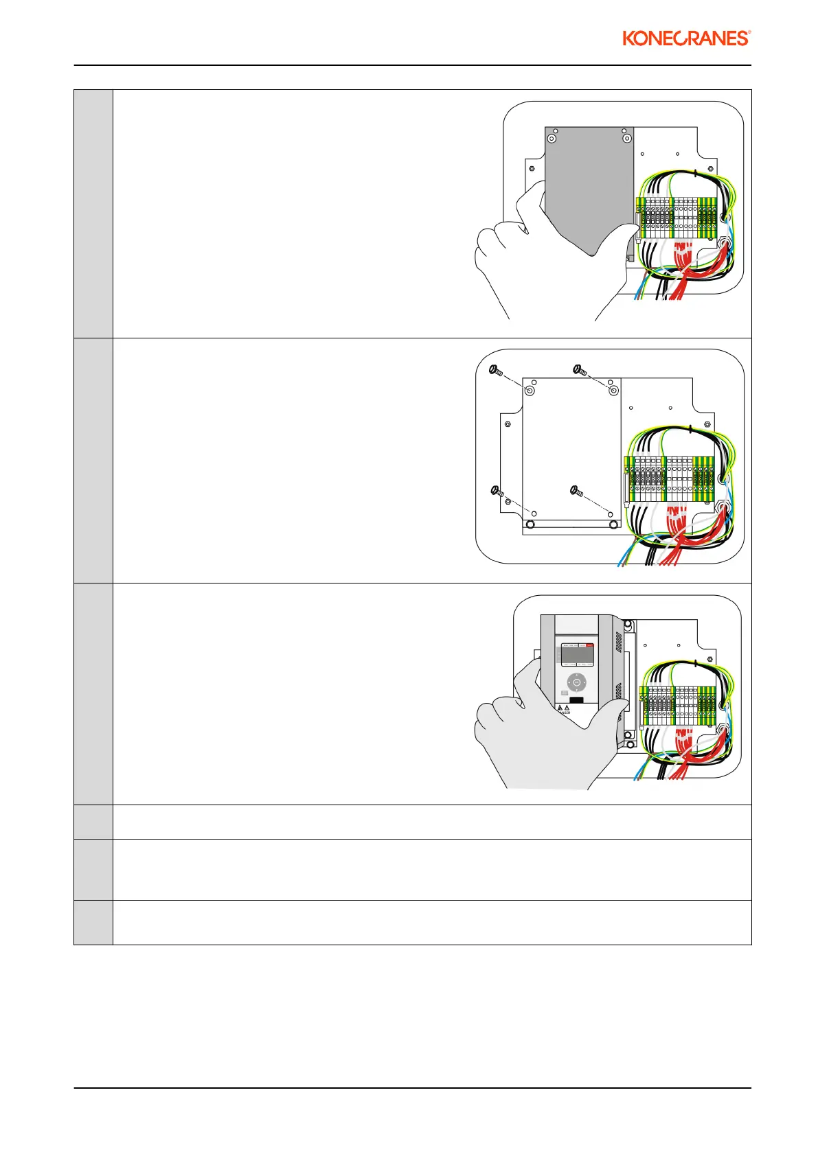
3
Put the installation rack (part 2) into place . Tighten the
screws.
4
Put 4 pcs, size M5 x 10 Flanged installation screws
into assembly rack. Leave screws loose. The inverter
has slotted screw holes.
5
Put the DynA45 006 into place. Tighten the screws.
6
Connect the power supply and motor wires in DynA45 according to electrical drawings.
7
Connect extra grounding wire from new inverter PE(protective earth) terminal to ground. Wire length
should not exceed 10 cm. The wire size should be minimum of 2.5 mm². This extra grounding wire is
not delivered with the package.
8
If the DynADrive 022 has an external braking resistor: Remove the internal braking resistor wires and
connect the braking resistor cable to DynA45 006 according to the electrical drawings.
020145en / Revision D / 2015-04-29
13/31
This document and the information contained herein, is the exclusive property of Konecranes Plc. and represents a non-public, confidential and proprietary trade secret that may not be
reproduced, disclosed to other parties, altered or otherwise employed in any manner whatsoever without the express written consent of Konecranes Plc.
Copyright
©
(2014) Konecranes Plc. All rights reserved.