E-1
INSTALLATION MANUAL
/
A6VF-9581-00
<Important>
Be sure to correctly follow the procedures in order as explained in this Installation Manual.
If you do not follow the procedure in order, the image trouble may occur.
35S9492 Rev001
I. Outline of installation procedures
When installing the machine and associated options as a system, follow the order shown on the upper.
Note:
• For the detailed installation procedures for each option, follow the instructions given in the corresponding
installation manual and perform the procedures correctly. (Optional devices must be installed after com-
pleting the main unit installation.)
• Once the Power Switch is turned ON, do not turn OFF it until the installation work has been completed.
Caution:
• Lifting the machine in an awkward position or transporting it in a poorly balanced position could result in
personal injury. When transporting the machine, assign an adequate number of persons to the job and
ensure that each person can take a good position of not being excessively loaded (mass: approx. 24 kg
(52-15/16 lb))
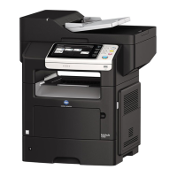
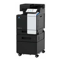
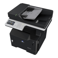
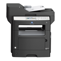
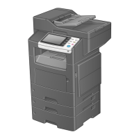
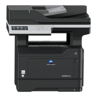
Machine
FS-P02
KP-P01
PF-P11
PF-P12
FK-512 MK-P03
AU-201
DK-P02
Applied Machines: /
E-2
II. Installation space
To make it easier to control, replace the
consumables, inspect, and etc., maintain some
space for installation shown below.
III. Pre-installation check items
1. Select a level and stable place for installing the
machine.
2. Be sure to use a power source of the voltage and
frequency indicated in the product specifications.
Ensure that the current carrying capacity of the
power outlet is at least equal to the current listed
in the product specifications.
3. Power the machine directly from a dedicated
power outlet. (Do not use an extension cord.)
4. Do not plug or unplug the power cord with wet or
dirty hands, otherwise you may get an electric
shock.
5. Avoid a hot and humid environment, or a place
exposed to direct sunlight.
6. Avoid a dusty location, or a place near volatile
and flammable substances.
7. Avoid a poorly ventilated place.
IV. Notes on using touch panel
Be sure to instruct users on the following points.
• This machine uses a capacitive touch panel.
When you touch the touch panel, use your fin-
ger or the stylus pen for the capacitive touch
panel. If you touch the panel using your nail or a
pen tip instead of using your finger or the stylus
pen, the touch panel does not respond nor-
mally.
• Pressing the touch panel hard may cause dam-
age.
• Do not strongly press the panel or press it using
the sharp tip of mechanical pencils.
• The key is a finger tapping (quick light touch
using a finger) operation.
No. Direction Space to maintain
1 Right 300 mm (11-13/16 inches)
2 Front 510 mm (20-1/16 inches)
3 Left 200 mm (7-7/8 inches)
4 Rear 200 mm (7-7/8 inches)
When the optional finisher is
mounted
: 270 mm (10-5/8 inches)
5 Top 800 mm (31-1/2 inches)
5
4
1
2
3