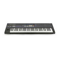
DW-6000
port
functions are
as
follows:
Port
A
(PA0~PA7):
The
keyboard
matrix and
switch
ma-
trix
input
port. IC9
and
IC10
(4050)
are non-inverting
buffers.
Port
B
(PBO
—
PB3) : A
4-bit
output
port for switch
matrix
row
control
signals.
Decoding
is
per-
formed
by IC11
(LS138)
and
IC12
(LS139),
which have
12
outputs.
TXD,
RXD:
Serial
I/O data terminals
for MIDI OUT
and
MIDI
IN,
respectively. MIDI
IN/OUT and
MIDI
THRU
circuits consist
of the photo-
coupler PCI
(TLP552)
and
IC14 (LS09)
AND
circuit.
Port
C: The
two
bits handled
by
PC5
and PC6 are
for
the tape
interface output terminal
(TO
TAPE), with
Q1 (C2785)
and
C7 (0.047ju)
used
for
conversion to
audio level.
PC7
is
for
the
tape
interface input terminal (FROM
TAPE),
with
1
C
1
6
(4558),
DB4 (MC931),
and
DB5
(MC921)
used
for
wave shaping from audio
level
to square wave.
AN0~AN3: A/D
converter input terminal
for input
of
joystick
x,
y,
tune
control, and slider variable
resistors.
1/2
I
Cl
7
(4558)
determines joystick
center value.
AD0~AD7:
This
terminal
is
for
the
lower
8-bit
address
bus
and
data
bus. The
lower
address
bus
is
latched by
IC6
(LS373).
AB8~AB15:
Upper
address
output
port. Performs
ROM
and RAM
addressing
with
AB8
^
AB12
and
chip
selection
with
AB13
~
AB15.
IC2
(2764)
is
an
EPROM
chip
containing
the
data and
system program
for
operating
the
CPU
(IC1
(/iPD7811)).
IC3
(HM-6116)
is
RAM
for
storage
of
user
created
sound
data,
protected
by
the CR2032-F1
backup
battery.
IC7
(H374)
works
as an
interface
between CPU1 and
CPU2.
IC18
(S-8054HN)
is
a 3-terminal
1C
for
system
resetting:
IC17
(4558)
and
Q2,
Q3
(A1175)
are
used for MIDI
power
supply;
at the
same time
this
is
input
to
the CPU
AN4
terminal
for
leading
edge
detection.
(2)
KLM-654:
This
board
contains
the
DWGS basic
system. The purpose
of
this system
is
to
get
pitch
and waveform
data
from the
CPU
bus
and
output
a cyclic
(repetitive)
waveform of
con-
stant
amplitude.
Oscillator operation
The PAI
(phase
angle
increment) value
and
PAR (phase
angle register) value
are
added and
the result
is stored
again
in the PAR.
The
PAR
value
is
used
as
the
wave
table
ad-
dress. The wave table
stores
different harmonic
configura-
tion
data
for
each octave
on
the keyboard.
IC29 (MB64H129)
performs
the processing
needed to
use
the
PAR
value
as
the wave table address.
Finally,
data read from
the wave table
is
converted
to an
analog
waveform
by
a
D/A
converter.
Time division
multiplexing enables dual
oscillator 6-voice
sound source capability.
(Maximum simultaneous output of this
system is
8
voices
x
2
oscillators.)
Note: Given
a
sampling frequency of
50
kHz, PAI
data
N
=
2
1
8
x
f/50
x
10
3
(where
f
is
the
pitch
frequency)
is
rounded
to
an integer value for N and converted
to a hexadecimal
number.
CPU
BUS
IC32
(MB62H133)
......
.74LS189X
10
IC33-IC37,
IC39-IC43
IC32
(62H133)
IC31
(64H129)
.64
K ROM
IC29,
IC30
.0
AC-08
HC138
+
4066
+
072
The main
LSI chips
are
the
CMOS
gate
array
IC31 (MB-
64H129)
and
IC32 (MB62H133),
the
wave-table
256K
mask
ROM
IC29
and
IC30 (HN613256),
the ten
TTL
64-
bit
RAM chips
for PAI
&
PAR
(IC33~IC37,
IC39~IC43;
S189), the
8-bit
D/A
converter IC28
(D
AC-08), decoder
chips
IC38,
IC44
(LS244), IC16
(LS175),
IC14,
IC15
(LS138), as
well
as
S/H
analog
switches
(IC11~IC13;
4066)
and
OP
AMPS
(IC5-IC10;
072).
IC32
(MB62H133) is
a
64-pin
LSI
with
about
800
gates
handling major
aspects
of the
system
including
the CPU
interface,
timing
generation,
and
adder.
-
27
-