3 41 2
1-1
Accessory
5 6
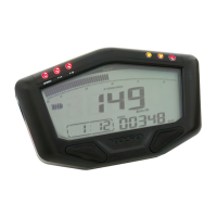
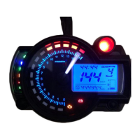
LCD meter X 1
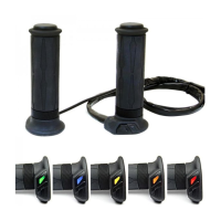
RPM wire set (A TYPE ) X 1 RPM wire set B TYPE X 1
Power wireX1
Temp sensor wire set X 2
PT 1/8water temp
sensor X 2
17
Mid-way connect X 2
1110
9
M5X5L Hexagon socket
screw X 2
M8/ S type speed
sensor X 1bracket
M10/ S type speed
sensor X 1bracket
12
2.5 mm spanner X 1
14 15
13
4 mm spanner X 1
Meter 1bracket X
M5 washer 2 X
16
M5 X 15L screw X 2
8
D6 X 5L mm magnet X 6
7
Reed switch speed
se
nsor X 1
18
M5 x 12L screw X 2
1-2
Option accessory
2
5/16-18 X 22.1L
M5 X P0.8 X 12L
M6 X P1.0 X 12.6L
M6 X P1.0 X 19.7L
M6 X P1.0 X 24L
M8 X P1.25 X 22.5L M8 X P1.25 X 27.5L
M8 X P1.25 X 29L M10 X P1.25 X 28.3L
Disc magnet screw
5
M14
M16.M18
M22.M26 mm
Water temp
sensor adapter
4
M12 X P1.5 X 15L
M14 X P1.25 X 15L
M14 X P1.5 X 15L
M16 X P1.5 X 15L
M18 X P1.5 X 15L
M20 X P1.0 X 15L
M20 X P1.5 X 15L
Oil temp sensor
adap
ter
6
M10 X P1.0
M12 X P1.5
M14 X P1.25
M14 X P1.5
M16 X P1.5 / M18 X P1.5
Temp sensor
7
Temp sensor wire set
(2 M)
Active speed sensor
3
L TYPE speed sensor
backet
1
Some of the option accessories may not sell. For the details, please contact the local distributor.
The advantage of the active speed sensor is as following, 1. You don't need to install the magnet in the opposite position of the speed
sensor. 2.
You could set up the sensor signal input up to 60 points, and the speed displayed will be more accurate. Please note that the
speed sensor attached in the kit is passive speed sensor, and the maximum speed signal it could read is 6 points.
NOTE
NOTE
Attention!
● For installation, please follow the steps described. Any damage caused by wrong installation shall be imputed to the users.
● To avoid a short circuit from occuring do not pull or modify the wires during installation.
● Do not disassemble or change any parts. Opening and dissassembling this unit will void any warranty.
● Maintenance and repairs should be executed by our professionals only.
◎ Symbol description:
NOTE
WARNING!
Some procedures must be followed to avoid damages to the instrument.
Certain procedures must be followed to avoid damages to yourself, to the vehicle or others.
HOLD THE
BUTTON 3
SECONDS
HOLD THE
BUTTON ONE
SECOND
Thank you for purchasing our product. This product is a multifunction meter and is easy to install. Before using, please read the instructions
carefully and retain them for future reference.
●