4
M8 / S type speed
sensor bracket X 1
NOTE
NOTE
NOTE
Put the magnet into the
brake disc screw hole.
Higher number of magnets installed on the disk brake will result in a faster speed display on the gauge.
The letter “N” on the magnets must face the speed sensor in order to pick up the speed corectly.
EX 1: If the disk brake has 3 screws, you can install 1 or 3 magnets.
EX 2: If the disk brake has 4 screws, you can install 1,2 or 3 magnets.
EX 3: If the disk brake has 5 screws, you can install 1 or 5 magnets.
EX 4: If the disk brake has 6 screws, you can install 1,2,3 or 6 magnets.
Install the s type sensor
bracket.
Adjust the sensor bracket
position to make sure
the sensor is facing the
magnet to receive good
speed signal.
Install the speed sensor
on the bracket.
In order to get a good
speed signal, the distance
between the speed sensor
and magnet should be
under 8 mm.
P.S.
EX. 1 EX. 2
EX. 3
EX. 4
2-1
Wiring installation instructions
YJDDC
1-1
Accessories
3
D6 X 5L mm magnet X 6
2
Speed sensor X 1
Mid-way connector X 10
11
1
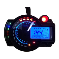
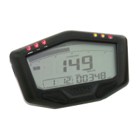
Meter X 1
7
Meter bracket X 1
6
M5 X 5L mm Hexagon
screw X 2
M10 / S type speed
sensor bracket X 1
5
8
M5 X 12L screw X 2
Meter (Accessories 1)
Speed sensor (Accessories 2)
Magnet (Accessories 3)
Mid-way connector (Accessories 11)
1-2
Optional accessories
5
Meter bracket
Contact your local distributor, if the items received in the box are not the same as the items listed above.
10
M5 washer X 2
9
M4 X 10L screw X 2
PRESS THE
BUTTON
ONCE
FLASH LIGHT ON
PRESS THE
BUTTON 3
SECONDS
2-2
Installation instructions
MOTO / SCOOTER
Magnet installation instructions
1
Active speed sensor
Please, follow the step-by-step instructions for proper installation. Any damages caused by faulty installation shall be imputed to the users.
Ɣ
To avoid a short circuit, do not pull the wires when installing the unit. Do not break or modify the wires either.
Ɣ
Do not disassemble or change any parts.
Ɣ
Maintenance and repairs should be executed by our professionals only.
Ɣ
æ
Notice
Thank you for purchasing the XR-01S. Before installing, please read the instruction carefully and keep them for future reference.Ɣ
Some of the optional accessories may not be available in your area. Contact your local distributor to obtain more information.
Some procedures must be followed to avoid faulty installation.
Some procedures must be followed to avoid damages from occuring to yourself and to others.
Some procedures must be followed to avoid damages from occuring to the vehicle.
If any information remains unclear, after following the instructions, please seek professional assistance.
ĻMARK MEANING:
Follow the steps below during installation.
Adjust the meter to the proper angle before tightening
the handle bar bracket screws.
4
Meter bracket
32
Disc magnet screw
L TYPE speed sensor
backet
NOTE
NOTE
YAMAHA
HONDA
SUZUKI
KAWASAKI
SYM
KYMCO
PGO
Main power switch wire reference:
Power
Ground
Brown
Brown
Black
Green
The colors listed above may differ depending
on the model and year of the vehicule.
Black
Black
Black
Black
Green
Green
Key on
Red
Red
Red
Red
Red / White
Orange
Green
Red / Black
White
Black / Yellow
Yellow / Green
YAMAHA
HONDA
SUZUKI
KAWASAKI
BMW
BENELLI
APRILIA
Light Blue
Yellow / Blue
Yellow / Black
Black
Gray / Violet
Gray / Violet
DUCATI
BUELL
CAGIVA
H-D
MV
Gray / Green
Gray / Green
Gray / Yellow
Pink
Pink
RedTRIUMPH
RPM wire reference:
The colors listed above may differ depending
on the model and year of the vehicule.
YAMAHA
SUZUKI
HONDA
Yellow / White
Yellow / White
The fuel sensor is electronic type, do not connect
in parallel with the original wire - otherwise
the fuel gauge won't display.
The wrong installation of the fuel
wire might damage the instrument.
Green
Fuel indicator wire reference:
KAWASAKI
SYM
KYMCO
PGO
Black / L Green
Gray
Yellow / White
Yellow / White
When connecting the power wire, follow the instructions carefully. If the red & brown wires are connected in parallel, the
meter will not work properly.
Red / Postive pole (Connect to the
battery DC 12 V
)
Black / Ground wire connect to the negative pole
of the battery (must be a good ground)
Brown / "+"Wire connect to
the DC 12 V
ignition switch
NOTE
N pole of the Magnet needs to be facing outward (facing the sensor) and must be installed on the brake disk or chain gear fixing bolt.
Orange - L turn signal
(+)
3XUSOH(QJLQHņ
Green - Fuel
Yellow - High beam
light (+)
Gray - Warning Light
9ņ
Blue - R turn signal (+)
White - Neutral
ņ
1.12 Nm (11.2 kgf.cm)
2.9 Nm (29 kgf.cm)
M5 X 12L screw X2 (Accessories 8)
Meter bracket (Accessories 7)
Fix the bracket on handle bar
M4 X 10L screw X2 (Accessories 9)
M5 washer X2 (Accessories 10)
Meter bracket (Accessories 7)
Meter X1 (Accessories 1)
1.12 Nm (11.2 kgf.cm)
2.9 Nm (29 kgf.cm)