Page 8
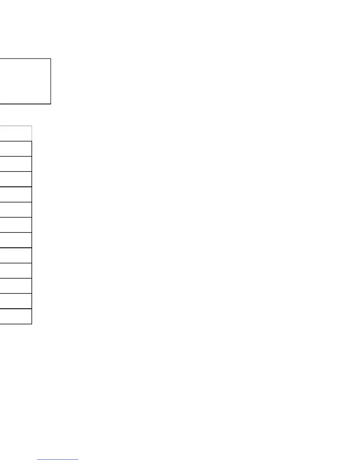
Table 1. Clearance Dimensions
Additional installation information can be found in the “Typical Installation Configura-
tions” section and your venting manufacturer/supplier’s literature.
INSTALLATION COMMENT: We recommend sufficient space be
provided (minimum 20 inches/500 mm) on each side of the heater to service
the equipment area. If this is not possible, a provision must be made to pull
the heater out for service.
Dimension Description Previa
A
Unit to side w all or side
facing
5" (125 mm)
B
Unit to back w all
1 " (25 mm)
C
Corner of unit to w all
1 " (25 mm)
D
Alcove height
48 " (1220 mm)
E
Overall unit height
30 " (760 mm)
F
Alcove depth (Maximum)
30 " (760 mm)
G
Alcove width
34" (865 mm)
H
Floor to centerline air intake
5.125 " (130 mm)
I
Floor to centerline exhaust
14.5" (370 mm)
J
Unit to mantle
N/A
K
Unit to top facing
N/A
All dimensions are minimum dimensions unless marked.