Manual KR-737+ radio navigation system
6
EN
Figures
Fig. 1: Panel controls ......................................................................................................... 9
Fig. 2: Remote control ..................................................................................................... 11
Fig. 3: Replacing the battery ............................................................................................ 12
Fig. 4: Behind the panel ................................................................................................... 12
Fig. 5: Source menu 1 ..................................................................................................... 13
Fig. 6: Source menu 2 ..................................................................................................... 13
Fig. 7: Inserting/take out a SD card ................................................................................. 14
Fig. 8: Connecting/Disconnecting a USB device .............................................................. 14
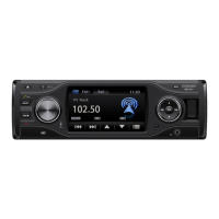
Fig. 9: Radio mode .......................................................................................................... 15
Fig. 10: Disc mode .......................................................................................................... 17
Fig. 11: Touchscreen control ........................................................................................... 18
Fig. 12: Disc playback menu ............................................................................................ 19
Fig. 13: ID3 tags .............................................................................................................. 20
Fig. 14: BT menu 1 .......................................................................................................... 23
Fig. 15: BT menu 2 .......................................................................................................... 24
Fig. 16: Dial ..................................................................................................................... 25
Fig. 17: Music playing via BT ........................................................................................... 26
Fig. 18: LOG/phone call history ....................................................................................... 26
Fig. 19: Equalizer ............................................................................................................ 27
Fig. 20: Fader/balance ..................................................................................................... 27
Fig. 21: Video settings ..................................................................................................... 27
Fig. 22: General settings menu ........................................................................................ 28
Fig. 23: DVD password .................................................................................................... 29
Fig. 24: Display calibration............................................................................................... 30
Fig. 25: ISO connector ..................................................................................................... 30
Fig. 26: Wiring diagram ................................................................................................... 32
Fig. 27: Parking brake wiring ........................................................................................... 33
Fig. 28: Reverse gear wiring ............................................................................................ 33
Fig. 29: Device installation ............................................................................................... 35
Fig. 30: Removing the device .......................................................................................... 35
Fig. 31: Removing the front panel .................................................................................... 36
Fig. 32: Re-attaching the front panel ................................................................................ 36
Fig. 33: Placing the GPS antenna .................................................................................... 37
Fig. 34: Installing the TMC hardware ............................................................................... 37
Fig. 35: Device reset........................................................................................................ 38
 Loading...