PSE-4 - Defining the PSE-4
4 Defining the PSE-4
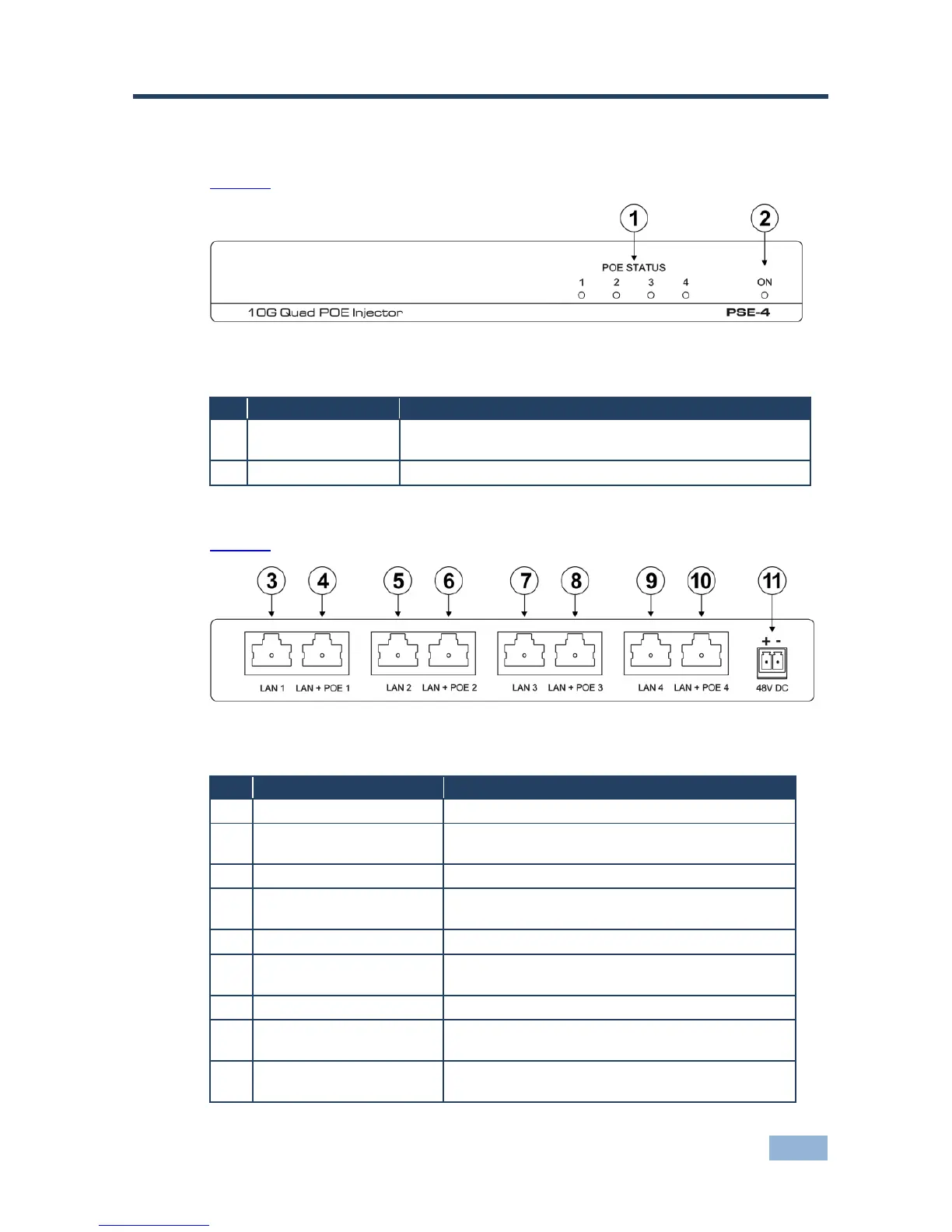
Figure 1 defines the front panel of the PSE-4 10G Quad POE Injector.
Figure 1: PSE-4 10G Quad POE Injector Front Panel
The relevant LED lights green when the PSE-4 provides
power over Ethernet to a remote device on that port
Lights green when the device is powered on
Figure 2 defines the rear panel of the PSE-4 10G Quad POE Injector.
Figure 2: PSE-4 10G Quad POE Injector Rear Panel
Connect to the first Ethernet/HDBT LAN
LAN + POE 1 RJ-45
Connector
Connect to the first Ethernet/HDBT LAN which is to
be powered by the PoE
Connect to the second Ethernet/HDBT LAN
LAN + POE 2 RJ-45
Connector
Connect to the second Ethernet/HDBT LAN which
is to be powered by the PoE
Connect to the third Ethernet/HDBT LAN
LAN + POE 3 RJ-45
Connector
Connect to the third Ethernet/HDBT LAN which is
to be powered by the PoE
Connect to the fourth Ethernet/HDBT LAN
LAN + POE 4 RJ-45
Connector
Connect to the fourth Ethernet/HDBT LAN which is
to be powered by the PoE
48V DC 2-pin terminal
block
Connect to the +48V DC power supply