Your SL-10 Master Room Controller
4 Your SL-10 Master Room Controller
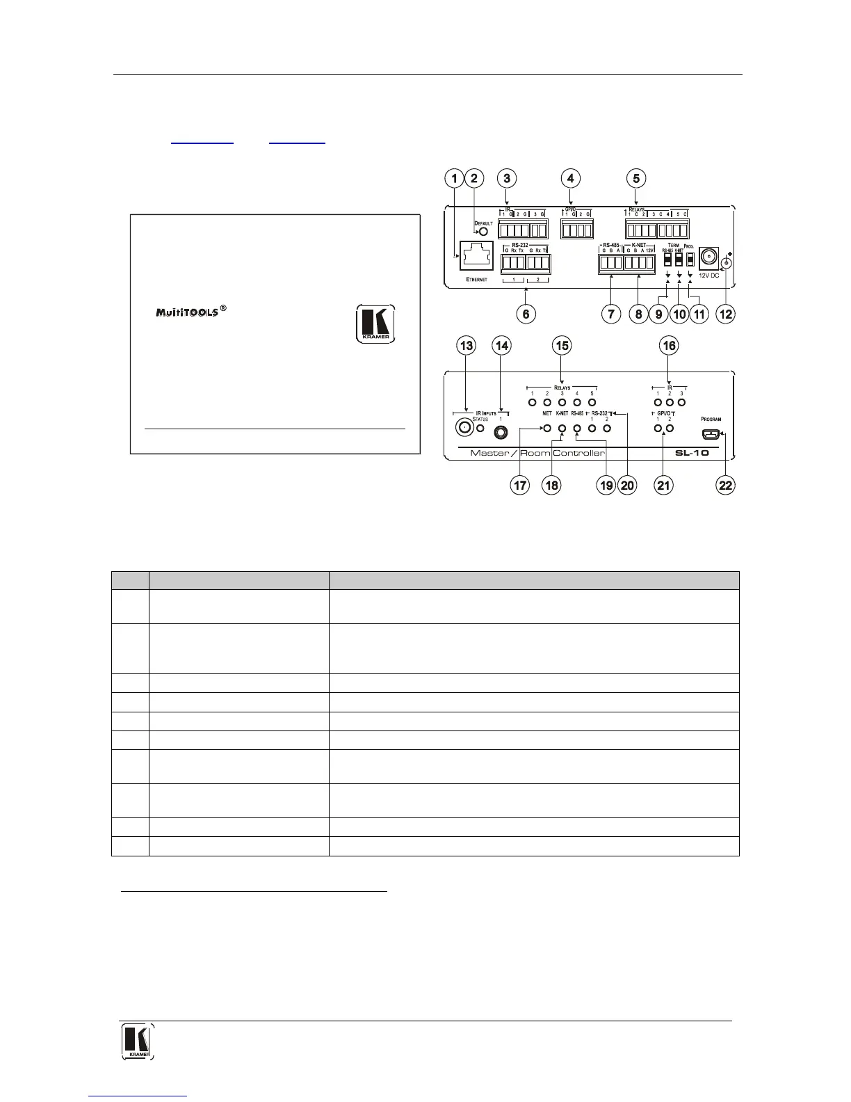
Figure 1 and Table 1 define the unit.
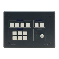
Figure 1: SL-10 Master Room Controller
Table 1: SL-10 Master Room Controller Functions
# Feature Function
1 ETHERNET RJ-45
Connector
Connects to the PC or other serial controller through computer
networking LAN to control several AV products over Ethernet
2 DEFAULT Recessed
Pushbutton
Press to reset to factory default definitions
1
3
:
IP number − 192.168.1.39, Mask – 255.255.0.0
Gateway – 0.0.0.0
IR Output Terminal Blocks Connect to IR emitter cables (from 1 to 3)
4 GPI/O Terminal Blocks Connect to various analog and digital sensors (from 1 to 2)
5 RELAYS Terminal Blocks Connect to low-voltage relay-driven devices (from 1 to 5)
6 RS-232 Terminal Blocks Connect to the RS-232 devices (from 1 to 2)
7 RS-485 Terminal Block Pins B (-) and A (+) are for RS-485; Pin G may be connected to the
shield (if required)
8 K-NET
PIN GND is for the Ground connection Connector
; PIN B (-) and PIN A (+) are
for RS-485, and PIN +12V is for powering other units
4
9
RS-485 TERM Switch Slides down for RS-485 termination, slides up for not terminated
10 K-NET TERM Switch Slides down for K-NET termination, slides up for not terminated
1 First disconnect the power supply and then connect it again while pressing the DEFAULT button. The unit powers up and
loads its memory with the factory default definitions and erases all stored presets
2 K-NET is a proprietary Kramer protocol for interconnecting Kramer units
3 The ground connection is sometimes connected to the shield of the RS-485 cable (in most applications, it is not connected)
4 Note that the SL-10 cannot receive power via the K-NET connector, but can power other units (but not another SL-10)
Tel. 07131 911201
Fax 07131 911203