PIN GND is for the Ground connection; PIN B (-) and PIN
A (+) are for RS-485, and PIN +12V is for powering other
units
Note that the SL-12 cannot receive power via the K-NET
connector, but can power other units (but not another
SL-12)
Slides down for RS-485 termination, slides up for not
terminated
Slides down for K-NET termination, slides up for not
terminated
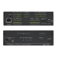
12V DC connector for powering the unit
IR INPUT Built-in receiver
and STATUS LED
Accepts IR remote commands (see Section 4.2)
Connect to an external IR receiver (1 and 2)
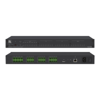
Illuminate when an relay is active (1 to 8)
Illuminate when an IR port is active
Illuminates while transmitting over Ethernet
Illuminates when the K-NET is active (red – transmit, green
– receive, during normal activity flashes red)
Illuminates while transmitting/receiving on an RS-485 port
Illuminate while transmitting/receiving on an RS-232 port
(1 to 4)
Illuminate while transmitting/receiving on a general
purpose I/O port (1 to 4)
Connect to a computer for unit configuration and firmware
upgrading