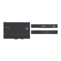
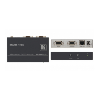
Figure 3: TP-125EDID XGA/Audio/Data Line Transmitter
Press to acquire the EDID information from the display
Illuminates during normal operation; flashes when acquiring the EDID
Illuminates when receiving power
XGA IN 15-pin HD (F) connector
Connect to the XGA source
Connects to the LINE IN RJ-45 connector on the TP-126 XGA/Audio Line Receiver
Use a CAT 5 cable with RJ-45 connectors at both ends
RS-232 terminal block connector
Connects to the PC or the Remote Controller
Connects to the audio source
+12V DC connector for powering the unit
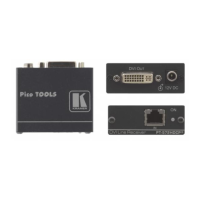
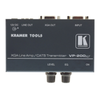
Figure 4: PT-110EDID XGA Line Transmitter
XGA IN 15-pin HD (F) Connector
Connect to the UXGA source
+12V DC connector for powering the unit
Press to acquire the EDID information from the display
Illuminates during normal operation; flashes when acquiring the EDID
Connects to the LINE IN RJ-45 connector on the TP-120 UXGA/Audio Line Receiver
Slide up to set the V SYNC to NEGATIVE polarity;
slide down to set the V SYNC to NORMAL polarity
By default, both switches are set down (for normal V SYNC and H SYNC polarity)
Slide up to set the H SYNC to NEGATIVE polarity (NEG);
slide down to set the H SYNC to NORMAL polarity
By default, both switches are set down (for normal V SYNC and H SYNC polarity)
Illuminates when receiving power
Step 3: Mount TP-121EDID, TP-123EDID, TP-125EDID, PT-110EDID
Install TP-121EDID, TP-123EDID, TP-125EDID, PT-110EDID using one of the following methods:
• Attach the rubber feet and place the unit on a flat surface.
• Fasten a bracket on each side of the unit and attach it to a flat surface
(see www.kramerav.com/downloads/TP-121EDID).
• Mount the unit in a rack using the recommended rack adapter
(see www.kramerav.com/product/TP-121EDID).
• Ensure that the environment (e.g., maximum ambient temperature &
air flow) is compatible for the device.
• Avoid uneven mechanical loading.
• Appropriate consideration of equipment nameplate ratings should be
used for avoiding overloading of the circuits.
• Reliable earthing of rack-mounted equipment should be maintained.