Step 4: Connect inputs and outputs
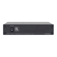
Always switch OFF the power on each device before connecting it to your TP-121EDID, TP-123EDID, TP-125EDID,
PT-110EDID.
Wiring the RJ 45 Connectors
This section defines the TP pinout, using a straight pin-to-pin cable with RJ 45 connectors.
The shielding must be connected/soldered to the connector shield.
To achieve specified extension distances, use the recommended Kramer cables available at www.kramerav.com/product/TP-121EDID.
Using third-party cables may cause damage!
Step 5: Connect power
Connect the power cord to TP-121EDID, TP-123EDID, TP-125EDID, PT-110EDID and plug it into the mains electricity.
Safety Instructions (See www.kramerav.com for updated safety information)
Caution:
• For products with relay terminals and GPI\O ports, please refer to the permitted rating for an external connection, located next to the terminal or in the User Manual.
• There are no operator serviceable parts inside the unit.
Warning:
• Use only the power cord that is supplied with the unit.
• Disconnect the power and unplug the unit from the wall before installing.