4 Your TP-50 XGA / Audio Line Receiver – DA
For a description of the TP-50 XGA / Audio Line Receiver – DA:
Topside, see section 4.1
Underside, see section 4.2
4.1 Your TP-50 XGA / Audio Line Receiver – DA Topside
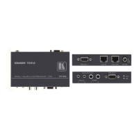
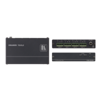
Figure 1 and Table 1 define the TP-50 topside:
Figure 1: TP-50 XGA / Audio Line Receiver – DA
Table 1: TP-50 XGA / Audio Line Receiver – DA Features
# Feature Function
1 12V DC +12V DC connector for powering the unit
2 LINE LOOP RJ-45 Connector Connect to the LINE IN RJ-45 connector of an additional
receiver to increase the number of outputs
3 LINE IN RJ-45 Connector Connect to the LINE OUT connector of a transmitter
1
4 XGA OUT 1 HD15F Connector Connect to the video acceptor 1
5 ANALOG 3.5mm Mini Jacks
Connect to the stereo analog audio acceptors (1 and 2)
6
AUDIO
OUTPUTS
S/PDIF RCA Connectors Connect to the digital audio acceptor (1 and 2)
7 XGA OUT 2 HD15F Connector Connect to the video acceptor 2
8 LINK LED Lights when receiving a valid input signal
9 ON LED Lights when receiving power
1 Using a straight pin to pin UTP or STP cable with RJ-45 connectors at both ends (the PINOUT is defined in Table 3 and Figure 4)