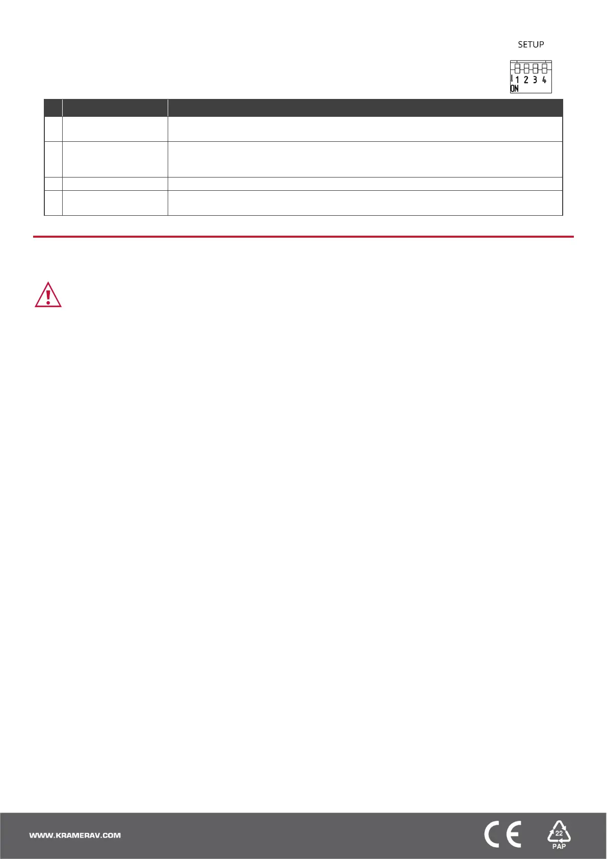
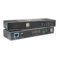
• All DIP-switches are set to OFF (up) by default except for the TP-590R DIP-switch 1 which is set to ON
(down) by default.
• Any changes to DIP-switches 1 and 4 require that you power cycle the device. Changes to DIP-switch 2
apply immediately.
OFF (up) – Host is active.
ON (down) – Host is not active (TP-590R default).
OFF (up) – Pass-through the IR signal to or from the IR cable.
ON (down) – Add IR modulation (38kHz) to the IR output signal (applies only when the IR port
is connected to an IR emitter cable).
Off (up) – FW programming RS-232 is inactive (Normal operation mode is enabled).
On (down) – FW programming RS-232 is active.
Step 5: Connect power
Connect the power cord to TP-590T and TP-590R plug it into the mains electricity.
Safety Instructions (See www.kramerav.com for updated safety information)
Caution:
• For products with relay terminals and GPI\O ports, please refer to the permitted rating for an external connection, located next to the terminal or in the User Manual.
• There are no operator serviceable parts inside the unit.
Warning:
• Use only the power cord that is supplied with the unit.
• Disconnect the power and unplug the unit from the wall before installing.


 To Previous Page