VM-218DTxr, VM-218DT – Connecting the HDMI/HDBT Switcher DA
3. Send an RS-232 command from the room controller to the display on the TP-780Rxr via
the HDBT OUT 7 port.
In the same way you can control other peripheral devices connected to the
transmitter/receivers.
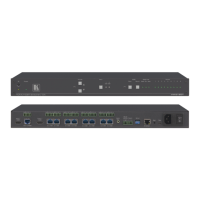
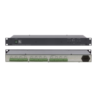
Controlling VM-218DTxr via RS-232 CONTROL
VM-218DTxr features an RS-232 CONTROL 3-pin terminal block connector allowing the
RS-232 to control the VM-218DTxr. To do so, connect the VM-218DTxr to a controller (for
example a PC) via the RS-232 CONTROL terminal block on the rear panel as follows:
• Pin 2 to the TX pin on the VM-218DTxr
RS-232 CONTROL terminal block.
• Pin 3 to the RX pin on the VM-218DTxr
RS-232 CONTROL terminal block.
• Pin 5 to the G pin on the VM-218DTxr
RS-232 CONTROL terminal block.
Wiring the RJ 45 Connectors
This section defines the HDBT pinout, using a straight pin-to-pin cable with RJ 45 connectors.
For HDBT cables, it is recommended that the cable ground shielding be connected/soldered
to the connector shield.