EasyManua.ls Logo

KROHNE BM 702 User Manual

KROHNE BM 702
40 pages
To Next Page IconTo Next Page
Page #1 background imageLoading...
Page #1 background image
DIN A4: 7.02224.32.00
©
KROHNE 01/2001 US size: 7.02224.72.00
GR/LD
This documentation is designed to help the user and/or systems
planning engineer select the optimum instrument type, assess
measurement properties, and plan the mechanical and electrical
installation.
Detailed information on installation, operation and control of type
BM 70 A/P, BM 702 Level-Radar instruments is contained in the
“BM 70 A/P or BM 702 Installation and Operating Instructions” and
the Short Manual “Getting Started with BM 70 A”, which are supplied
together with the instruments.
The structure of this documentation is modelled on the lines of DIN V 19259 V Standard.
Project Engineering
Guidelines
BM 70 A, BM 70 P, BM 702
LEVEL-RADAR
Contents: Page
1 Application range 2
2 Mode of operation and system structure 3
3 Input (measured quantity) 5
4 Output 6
5 Measuring accuracy 11
6 Application conditions 14
7 Design 23
8 User interface 34
9 Power supply 36
10 Certificates and approvals 38
11 Order information 39
12 External standards, codes and directives 40
13 Quality assurance 40

Other manuals for KROHNE BM 702

Question and Answer IconNeed help?

Do you have a question about the KROHNE BM 702 and is the answer not in the manual?

KROHNE BM 702 Specifications

General IconGeneral
Frequency26 GHz
Housing materialAluminum or stainless steel
Ingress protectionIP66/67
CommunicationHART, PROFIBUS PA, FOUNDATION Fieldbus
TypeFMCW Radar
Process connectionThreaded or flanged
Process temperature-40 to +200 °C
Process pressure-1 to 40 bar (-14.5 to 580 psi)
Accuracy±2 mm
Output4...20 mA/HART

Summary

Project Engineering Guidelines

Application Range Overview

Mode of Operation and System Structure

Measurement Principle: FMCW Radar

Explains the Frequency Modulated Continuous Wave (FMCW) radar measurement principle.

Input Parameters and Measuring Ranges

Output Signal Variants and Communication

Output Variants for BM 70 A/P

Lists and describes the different output variants available for BM 70 A/P.

Output Variants for BM 702

Lists and describes the different output variants available for BM 702.

Ex-e Current Output HART® (BM 70 A/P)

Details the function, current, accuracy, and supply voltage for Ex-e HART® output.

Ex-i (IS) Current Output HART® (BM 70 A/P)

Details the function, current, accuracy, and supply voltage for Ex-i HART® output.

Ex-i (IS) Current Output HART® (BM 702)

Details the function, current, and supply voltage for BM 702 Ex-i HART® output.

Measuring Accuracy Specifications

Error of Measurement Charts (BM 70 A)

Graphical representation of measurement error as a function of distance for BM 70 A.

Error of Measurement Charts (BM 702)

Graphical representation of measurement error as a function of distance for BM 702.

BM 70 A Precision Accuracy

Accuracy specifications for BM 70 A with special calibration.

BM 70 P Accuracy

Accuracy specifications for BM 70 P.

Application Conditions and Installation

Recommendations for Positioning on Tank (Horn/Wave-Stick)

Provides guidance on positioning horn antennas or Wave-Sticks relative to tank walls.

Mounting on Tank Fitting (Horn Antenna)

Specifies how to mount horn antennas on the tank fitting and project them.

Mounting on Still Wells

Details antenna types and outside diameters for still well mounting.

Hazardous Location Approvals (ATEX)

Lists zones, temperature classes, and danger groups for hazardous location use.

Ambient Temperature of Signal Converter

Specifies ambient temperature limits for standard and special signal converter versions.

Flange Temperature Limits

Details minimum and maximum flange temperatures for various antenna and gasket types.

Product Limitations and Operating Pressure

Product Limitations for Radar Measurement

Lists specific products unsuitable for radar-based level measurement.

Maximum Allowable Operating Pressure

Details maximum operating pressures for flange systems and Wave-Sticks.

Device Design and Models

Available Models: BM 70 A/P, BM 702

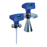
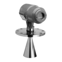
Shows images of the different BM 70 models: horn antenna, Wave-Stick, Wave-Guide.

Antenna Type and Size Selection Guide

Antenna Selection for BM 70 A

Recommends antenna types for BM 70 A based on application experience and tank type.

Antenna Selection for BM 70 P

Recommends antenna type 4 for BM 70 P and specifies still well requirements.

Electrical Connection and Terminal Assignment

Available Accessories

PC-CAT Configuration Software

Details the features and usage of the PC-CAT software for configuration and monitoring.

User Interface and Operator Control

Operator Control Methods

Explains various methods for controlling the device, including PC-CAT and bar magnets.

Parameter Setting for Configuration

Supply Power Options and Technical Data

Supply Power Versions and Specifications

Details the available supply power versions (24V DCAC, 115/230V AC) and their ratings.

Fuses and Safety Notes

Insulation Rating and Class of Protection

Details insulation ratings according to VDE and class of protection.

Power Supply Safety Considerations

Covers safety aspects for DC/AC and AC power supplies, including hazardous-duty systems.

Certificates and Approvals

Hazardous Duty Approvals (ATEX)

Lists country-specific approvals for hazardous locations, including ATEX.

Order Information and Application Data

Technical Information for Ordering

Summarizes technical details required for ordering BM 70 A/P, BM 702.

Additional Application Assessment Data

Lists tank dimensions and operating data needed for application assessment.

Related product manuals