BM 70 X Project Engineering Guidelines 01/2001 Page: 3
2 Mode of operation and system structure
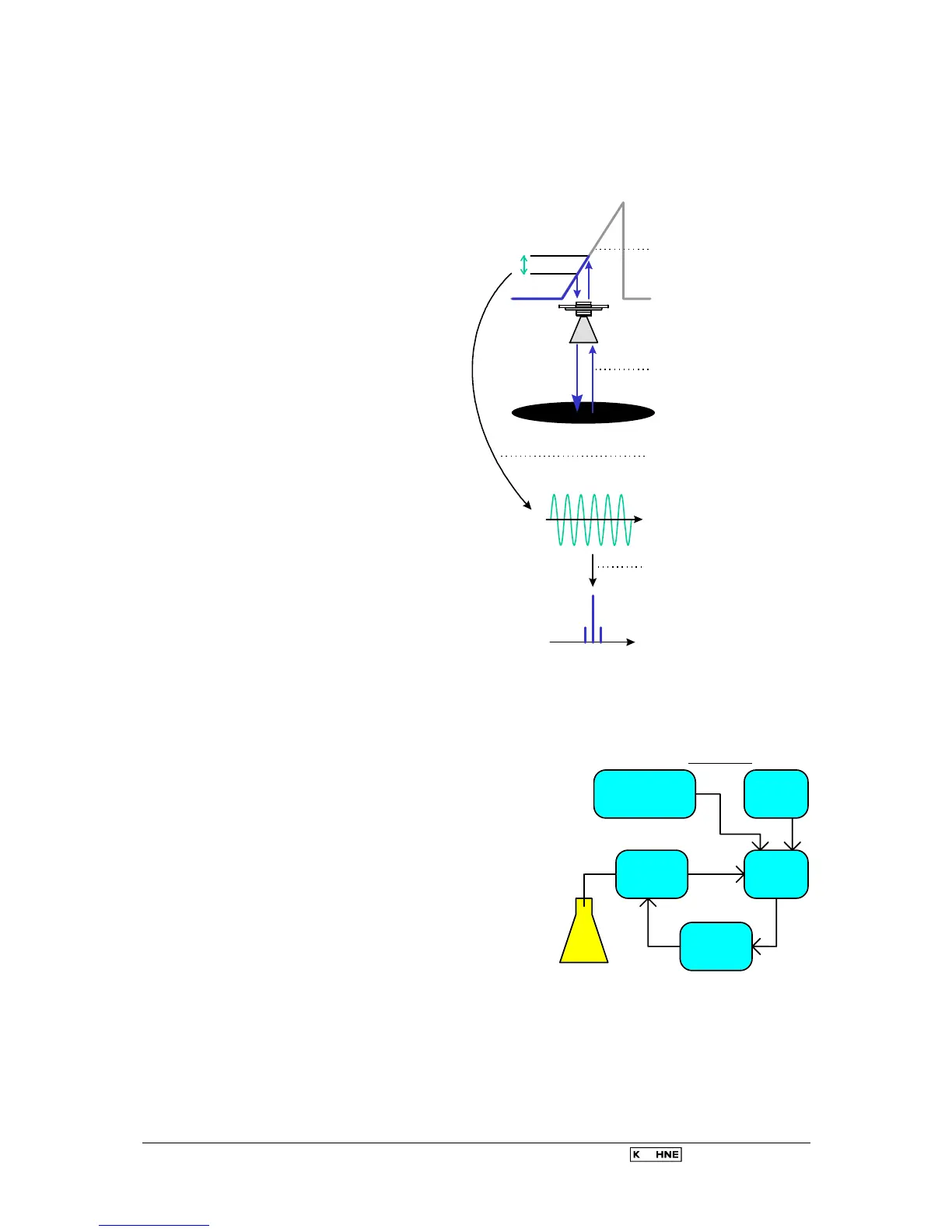
2.1 Measurement principle (FMCW Radar)
A radar signal is given via an antenna,
reflected on the measuring surface
and received after a delay time t.
FMCW: Frequency Modulated
Continuous Wave
The FMCW-radar uses a high
frequency signal (
∼
10 GHz) which
transmit frequency increasing linearly
1 GHz during the measurement
(frequency sweep) (1). The signal is
emitted, reflected on the measuring
surface and received time-delayed (2).
For further signal processing the
difference
∆
f is calculated from the
actual transmit frequency and the
receive frequency (3). The difference
is directly proportional to the distance
i.e. a large frequency difference
correspond to a large distance and
vice versa.
The frequency difference is
transformed via a Fourier
transformation (FFT) into a frequency
spectrum and then the distance is
calculated from the spectrum.The
level results from the difference
between tank height and distance.
Linearity of frequency sweeps
The measuring accuracy of a FMCW radar is determined
from the linearity of the frequency sweeps and their
reproducibility. The linearity correction is deduced via
reference measurement of the oscillator. The non-linearity
is corrected up to 98% (BM 702/BM 70 A).
An immediate frequency regulation is necessary with the
BM 70 P device because of the higher demand on the
measuring accuracy.
With the PLL technology (Phase Locked Loop) the signal
frequency is directly recorded as a digital data and the
converter oscillator locks automatically on the right
frequency.
As the transmit frequency is changed during a short time
interval by FMCW radar the transmitted frequency has to
follow the nominal frequency within micro seconds. This
ensues via modern, fast electronic and processors.
∆
f
Time signal
Spectrum
t
f
1) Radar frequency is
modulated linearly
2) Delay time due to
wave propagation
3) Resulting difference
frequency
4) Digital signal
processing
5) Level is
calculated
FFT
Microprocessor
control
Reference
oscillator
Phase
detector
Microwave
oscillator
Loop
filter
Antenna
PLL structure
 Loading...