Form #: SIDOM.4 Page | 10 Revised: 03/19
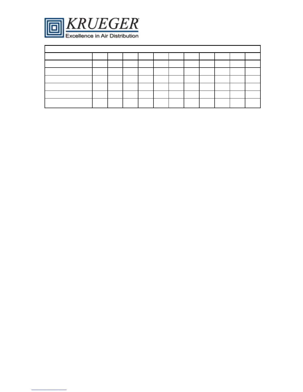
Inlet Airflow Sensor Area and K Factor
Recommended Min
CFM @ 0.03” WG
Table 1 – Inlet Airflow Sensor K Factor
System Calibration of Airflow Sensor
To achieve accurate pressure independent operation, the inlet airflow sensor must be calibrated to
the controller. This ensures that airflow measurements will be accurate for all terminals at system
start-up. System calibration is accomplished by calculating a flow coefficient that adjusts the
pressure fpm characteristics. The flow coefficient is calculated by dividing a unit’s design air volume
(in CFM at a differential pressure of 1” WG) by the standard Pitot tube coefficient of 4005.This ratio
is the same for all sizes, no matter which probe type is installed. Calculate the design air velocity by
dividing the design air volume by the nominal inlet area (in sq. ft.). This factor is the CFM K factor
listed in the Table 1 above.