Form #: SIDOM.4 Page | 19 Revised: 03/19
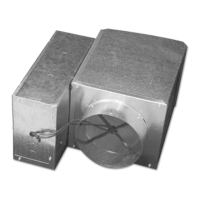
4. Connect the wires to the terminal block. Refer to the wiring diagram located inside the control
enclosure of each unit which shows the wiring terminations. The wiring schematic can also be
found on the control sequence submittal on the Krueger website.
5. Replace the thermostat cover. Turn the two hex screws COUNTER CLOCKWISE until they are
flush with the bottom of the cover to secure it to the back plate.
Programming Thermostat
1. The thermostat has three sequences that are selectable from the display screen. To access the
configuration menu on the thermostat, press and hold the Up and Down arrows simultaneously
for 10 seconds until the display starts flashing “LIMITS”. Use the Up and Down arrows to scroll
between the different menu options or set a specific value. Use the Setpoint button to select a
menu or set a value.
2. To set the minimum and maximum airflow limits, use AO1 Min and AO1 Max or AO2 Min and
AO2 Max. Use the following Table 4 to determine the corresponding thermostat setting for the
CFM per inlet size.
3. For details on how to program the thermostat for each control sequence refer to the specific
control sequence submittal. The control sequence submittals can be on the Krueger Website:
www.krueger-hvac.com.
NOTE: Default Settings are as follows:
AO1 – MIN=0, MAX=12, AUX=0
AO2 – MIN=0, MAX=12
DEAD BD (deadband) = 2° F
SETBACK (standby/unoccupied setback) = 2° F
PROP BD (loop proportional band) = 2° F
Rm OFST (room temperature offset) = 0
CNG OVR (changeover temperature) = 77° F
ITIME (loop integral time) = 30 minutes