Do you have a question about the KS LEV Ci and is the answer not in the manual?
Highlights the high-performance nature of the product and the importance of proper installation and maintenance.
Emphasizes the need for regular maintenance by a qualified technician and warns against disassembly.
Details frame compatibility, warns against modifications, and stresses frame cleanliness for proper seatpost installation.
Provides specific guidance on applying grease to threads and using friction paste for LEV-Ci models, including torque specs.
Illustrates the correct orientation for LEV-Ci, LEV Integra, LEV-Si, e30-i, Crux-i, and eTen-i models.
Explains the importance of inserting the seatpost to the minimum insertion line to prevent damage and ensure safety.
Advises tightening the seat collar to a maximum of 5 N-m to avoid inhibiting proper seatpost function.
Encourages reading instructions carefully and seeking assistance if unsure about installation skills or tools.
Strictly warns against drilling or modifying the frame, as it voids warranties and can cause failure, injury, or death.
Guides on temporarily installing the remote lever and routing the elbow noodle and cable housing for length measurement.
Specifies torque for hinged and non-hinged lever clamps and describes compatibility with ODI Lock-On grips.
Explains how to integrate the alloy remote lever clamp with ODI Lock-On compatible grips by replacing the inner lock ring.
Details routing the cable housing through the bicycle frame according to manufacturer specifications, ensuring sufficient length.
Instructs on marking the cable housing at the seat collar and an additional 110mm for final cutting.
Details installing the ferrule onto the end of the cable housing at the seat collar after it has been routed through the frame.
Explains feeding the inner wire through the remote lever, barrel adjuster, and housing, then pulling slack from the seat collar.
Details trimming cable housing and inner wire for standard shifter cables, including torque for the locking cable end.
Provides instructions for using a standard shifter cable, marking the inner wire 18mm longer than housing.
Details installing the LEV-Ci ferrule and routing the Recourse inner wire, with specific spacing for the locking cable end.
Guides inserting the Locking Cable End through the slotted hole and the housing into the slotted cable stop on the mast.
Details placing the seatpost into the seat collar while managing cable slack from the frame entry point.
Explains removing and reassembling the saddle clamp components, including spherical nuts and floating clamps.
Guides on seating saddle rails, achieving the desired angle, and tightening head clamp bolts to specified torque (10 N-m or 8 N-m for LEV-Ci).
Details loosening the head clamp bolts, setting saddle position, and tightening to 15 N-m for CRUX-i models.
Details loosening the single head clamp bolt, setting saddle position, and tightening to 22 N-m for eTen-i models.
Guides on adjusting air pressure using a shock pump for LEV-Ci, LEV Integra, and LEV-Si models, with recommended operating pressures.
Explains the initial 'nudge' required for first-time use or after long periods of non-use due to seal migration.
Details how to lower and raise the saddle using the actuation lever or remote for any desired position within travel.
Outlines checks for seat post security, bolt tightness, wear, leaks, and proper maximum raised position for control.
Recommends periodic service, cleaning, and lubrication every 6 months, with more frequent maintenance for wet/dusty conditions.
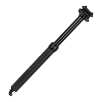
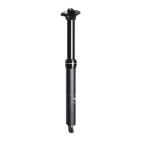
The KS Height Adjustable Seatpost is a precision piece of cycling equipment designed to allow riders to adjust their saddle height on the fly, enhancing control and comfort across varied terrain. This user manual covers several models, including LEV-Ci, LEV Integra, LEV-Si, e30-i, Crux-i, and eTen-i, all of which are height-adjustable seatposts. The primary function of these seatposts is to provide dynamic saddle height adjustment, which is particularly beneficial for mountain biking, allowing riders to quickly lower their saddle for descents and technical sections, and raise it for climbing and flat terrain.
The core function of the KS Height Adjustable Seatpost is to provide a variable saddle height. This is achieved through an internal mechanism that allows the seatpost to extend or retract, controlled by a remote lever typically mounted on the bicycle's handlebar. When the lever is actuated, the rider can apply weight to the saddle to lower it or unweight it to allow it to extend to a desired position. The LEV-Ci, LEV Integra, and LEV-Si models, in particular, feature an adjustable return speed, allowing riders to customize how quickly the saddle extends. This adjustment is made by accessing an air valve at the top of the stanchion tube, where a compatible shock pump can be used to set the desired air pressure within a recommended range of 100-250 psi, not to exceed 250 psi. The internal cable routing, common across all Integra models, ensures a clean aesthetic and protects the cable from external damage, contributing to reliable performance.
Before installation, it is crucial to ensure the seatpost is compatible with the bicycle frame's seat tube inner diameter. LEV Integra models are designed to fit 27.2mm, 30.9mm, 31.6mm, or 34.9mm seat tubes. Proper fit is essential to prevent slippage, faulty performance, and potential injury. The manual explicitly warns against modifying the bicycle frame, as this can void warranties and lead to frame failure.
Installation begins with proper seatpost orientation. Since Integra models feature internally routed cables that are in-line with the seatpost, there is only one correct position for saddle orientation, ensuring the saddle points forward. Minimum insertion distance is critical; all seatpost models must be inserted into the seat tube to cover the minimum insertion line indicated on the seatpost. Failure to do so can damage the seatpost and/or bicycle and may result in loss of control. The seat collar should be tightened to a maximum torque of 5 N-m to avoid inhibiting proper seatpost function.
Cable and housing length determination is a multi-step process. The remote lever is temporarily installed on the handlebar (either right or left side) to determine the appropriate cable length. The housing is routed through the frame according to the bicycle manufacturer's specifications, ensuring it is long enough to wrap around the head tube without impeding steering. Once the housing is marked at the seat collar, an additional 110mm is measured towards the handlebar, and the housing is cut to this final length.
Connecting the inner wire involves feeding it through the remote lever, integrated barrel adjuster, and cable housing. For standard shifter cables, the inner wire is marked 18mm longer than the cable housing (or using a molded gauge on the protective cap) and a locking cable end is tightened to it using 3mm and 2mm Hex wrenches, ensuring the inner wire is flush. For the Recourse Ultralight cable system, the LEV-Ci ferrule is installed, and the inner wire is routed, leaving 13mm spacing before tightening the locking cable end. The locking cable end is then inserted through a slotted hole in the mast, and the housing is inserted into the slotted cable stop. Finally, the seatpost is placed into the seat collar, taking up cable slack.
Saddle installation varies slightly by model. For LEV-Ci, LEV Integra, LEV-Si, and e30-i, the two saddle head clamp bolts, spherical nuts, and upper and lower floating clamps are removed using a 4mm Hex wrench. The saddle rails are then placed between the upper and lower floating clamps, and the components are reassembled. The head clamp bolts are tightened evenly to achieve the desired saddle angle, with a maximum torque of 10 N-m (8 N-m for LEV-Ci). For Crux-i, a 5mm Hex wrench is used to loosen the two head clamp bolts, allowing for fore/aft and angle adjustment, then tightened to a maximum of 15 N-m. For eTen-i, a 6mm Hex wrench is used to loosen the single head clamp bolt, allowing for similar adjustments, then tightened to a maximum of 22 N-m.
For first-time use or after a long period of non-use, a firm downward "nudge" may be required to initiate movement, as the seal's natural tendency is to migrate oil away from the surface. Once cycled through its travel, the seatpost will function normally. To lower the saddle, the rider applies weight while pressing and holding the actuation lever or remote. To raise it, the rider actuates the lever or remote and unweights the saddle. The saddle can be set to any desired position within its travel.
The KS Height Adjustable Seatpost is a high-performance product that requires regular maintenance to ensure reliable service and consistent function. The manual emphasizes that maintenance should be performed by a qualified service technician, and disassembly by the user is strictly prohibited due to internal pressure and potential for damage or injury, which would also void the warranty.
Before each ride, riders should check that the seatpost is securely fastened in the frame, all clamping bolts are tightened to their specified torque values, and there are no signs of excessive wear or leaks. The seatpost's proper function should be verified, and the maximum raised position should be checked to ensure it is not too high for the rider to maintain control.
Periodic maintenance is essential. Routine service should be performed at regular intervals, with the duration depending on frequency of use and riding conditions. Generally, the seatpost should be cleaned and lubricated at least once every six months. More frequent maintenance is recommended for wet or severely dusty conditions, or if a high-pressure water sprayer is used to wash the bicycle, as this increases the chance of water ingress into the system. If any degradation of performance is observed, maintenance should be performed as soon as possible.
KS Suspension provides detailed installation and service videos for all models on their website, http://kssuspension.com/support/tech-info/, to assist with maintenance procedures. For further assistance or to locate a qualified service technician, riders can contact their local Service Center, with contact information also available on the KS Suspension website, http://www.kssuspension.com.
| Category | Dropper Seatpost |
|---|---|
| Diameter Options | 30.9mm, 31.6mm |
| Material | Carbon Fiber |
| Actuation | Cable |
| Routing | Internal |
| Travel Options | 100mm, 125mm, 150mm |
| Activation | Remote |