Do you have a question about the KS LEV and is the answer not in the manual?
Regular maintenance by a qualified technician is mandatory; disassembly voids warranty and poses injury risk.
Ensure seat post is inserted to cover the minimum insertion line to prevent damage and loss of control.
Tighten seat collar to a maximum of 7 N-m; over-torquing inhibits function and voids warranty.
Lower saddle by weighting it and holding lever; raise by pulling lever while unweighted.
Adjust return speed using a shock pump on the air valve (150-250psi); LEV DX and 272 are not adjustable.
Check seat post security, bolt torque, wear, leaks, and proper function for safe control of the bicycle.
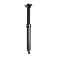
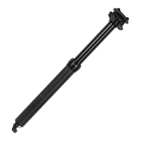
This document is a user manual for the KS Height Adjustable Seatpost, covering models LEV, LEV Carbon, LEV DX, and LEV 272. The manual provides comprehensive instructions for installation, operation, and maintenance of the seatpost, emphasizing safety and proper usage to ensure reliable performance and maintain warranty validity.
The KS Height Adjustable Seatpost is a high-performance bicycle component designed to allow riders to quickly and easily adjust their saddle height while riding. This feature enhances control and comfort across various terrains and riding conditions, such as descending steep trails or climbing ascents. The seatpost operates using an internal mechanism that allows for infinite height adjustment within its travel range, actuated by a remote lever mounted on the handlebar.
Before installation, it is crucial to ensure that the seatpost diameter (27.2mm, 30.9mm, 31.6mm, or 34.9mm) matches the bicycle's seat tube inner diameter. An improper fit can lead to slippage, faulty performance, and potential injury, and may void the warranty. The frame's seat tube must be clean, free of debris, and smooth to prevent scoring the seatpost. When inserting the seatpost, a friction or anti-seize compound should be applied to the inside of the seat tube and the inserted surface of the seatpost; grease should not be used in this area. All seatpost bolt threads, however, should be greased.
The seatpost must be inserted into the bicycle's seat tube to cover the minimum insertion line indicated on the post. Failure to do so can damage the seatpost and/or bicycle, potentially leading to a loss of control and serious injury or death. The frame's seat collar should be tightened to a maximum torque of 7 N-m. Over-tightening can inhibit the proper function of the seatpost.
The LEV seatpost offers flexible orientation within the seat tube, allowing for 20-degree incremental adjustments to accommodate various frame styles and cable routing configurations. After orienting the seatpost, the saddle needs to be installed and aligned to point forward. This involves removing the two saddle head clamp bolts, spherical nuts, and the upper and lower floating clamps using a 4mm Hex wrench. The lower clamp body may slide down the stanchion tube during this process. A flathead screwdriver is used to remove the air valve cap from the top end of the stanchion tube, which allows the lower floating clamp cradle and body to rotate freely for correct orientation. The low end of these components must point toward the front of the bicycle. Once oriented, the saddle rails are placed between the upper and lower floating clamps, seating them in the channel provided by the lower clamp. The head clamp bolts are then tightened to the maximum torque specified for the particular KS dropper post head clamp model, which may vary.
The remote lever, which controls the seatpost's height adjustment, can be installed with either a standard grip or an ODI LOCK-ON™ compatible grip. For standard grips, a 3mm Hex wrench is used to loosen and remove the pinch bolt, allowing the hinged lever clamp to be positioned on the handlebar. The pinch bolt is then reinstalled and tightened to a maximum torque of 4-5 N-m for LEV alloy remotes or 1 N-m for LEV Integra polycarbonate remotes. For ODI LOCK-ON™ compatible grips, the alloy remote lever clamp can replace the inner lock ring of the grip. It's important to note that polycarbonate remote lever clamps are not hinged and are not compatible with ODI LOCK-ON™ grips.
Cable installation involves routing a 1700mm long cable, 1500mm long cable housing, and an in-line barrel adjuster. The cable housing may need to be shortened to minimize slack. The housing is cut into two pieces to accommodate the in-line barrel adjuster, ensuring the total length is sufficient for proper routing from the remote lever to the seatpost. The inner wire is fed through the remote lever, integrated barrel adjuster, and cable housing. The required cable and housing length is determined by turning the handlebars to their most extreme position. The cable housing is trimmed to this measured length, but the inner wire is not cut at this stage.
There are two options for cable installation: using a standard shifter cable or the Recourse Ultralight cable system. For a standard shifter cable, the inner wire is cut to be 22mm longer than the cable housing. LEV's custom barbed ferrule, spring, and locking cable end are then installed, ensuring the inner cable does not protrude beyond the locking cable end, which is tightened using 2mm and 3mm Hex wrenches. For the Recourse Ultralight cable system, the custom barbed ferrule, spring, and locking cable end are installed, and the Recourse inner wire is routed as shown. The locking cable end is tightened, leaving 15mm spacing, and any excess inner wire is trimmed flush with the locking cable end.
Connecting the cable to the seatpost requires removing the cable junction cover. A small rod or Hex wrench may be needed to gently lift the cover. The cable clamp is located within the junction box, and the cable barrel is slid into its slotted end, ensuring the inner wire is seated in the center slot and both halves of the cable barrel are supported. The spring must be fully seated within the cable junction box. The inner wire and cable housing are pulled against the spring until the barbed ferrule can be slid into the slotted guide at the base of the junction box. The junction box cover is then reinstalled, observing the directional indicator inside the cap. The barb in the barbed ferrule is designed to fit within a small indent at the base of the junction box cover. Finally, the junction box cap is pushed down, and the barbed ferrule is pushed up to lock it in place. Care must be taken not to cut or pinch the o-ring dust seal; a small amount of grease can be applied if the seal is dry or prone to pinching.
When using the seatpost for the first time or after a long period of non-use, a firm downward "nudge" may be necessary to initiate movement. This helps to distribute oil on the seal and restore normal function. To lower the saddle, the rider weights the saddle or sits on the bike while pressing and holding the actuation lever or remote, releasing it at the desired height. To raise the saddle, the lever or handlebar remote is actuated, and the saddle is unweighted, releasing the lever at the desired height. The saddle can be raised and lowered to any desired position within the seatpost's travel.
The return speed of the seatpost can be adjusted on all LEV models, except LEV DX and LEV 272, which are not adjustable. To adjust, the air valve cap is removed from the top end of the stanchion tube using a flathead screwdriver. A compatible shock pump is then attached, and the pressure is adjusted to the desired return speed. KS recommends their AIR-8 High Pressure pump. Recommended operating pressures are 150-250psi, and this limit should not be exceeded.
Safety and maintenance are critical for the longevity and proper function of the seatpost. Before each ride, riders should check that the seatpost is secure in the frame, all clamping bolts are tightened to their specified torque values, and there are no signs of excessive wear or leaks. The seatpost's function should be checked, and the maximum raised position should not be too high for the rider to maintain control of the bicycle. Periodic maintenance is required to maintain consistent function and should be performed at the same interval as drivetrain cleaning by a local dealer or authorized KS Service Center. Further information and service center locations can be found on the KS Suspension website. Disassembling the seatpost is strongly warned against, as it can cause damage and severe personal injury due to internal pressure, and will immediately void the warranty.
| Type | Dropper Seatpost |
|---|---|
| Material | Aluminum |
| Actuation | Cable |
| Travel | 100mm, 125mm, 150mm |
| Diameter | 30.9mm, 31.6mm |
| Activation | Lever |