SETUP 2
5
F01629-10
– Remove the cardboard from around the shock absorber.
– Position the angle lever and linkage lever.
–
Mount and tighten fitting
1
.
Guideline
Nut, linkage lever
on angle lever
M14x1.5 60 Nm
(44.3 lbf ft)
–
Mount and tighten screw
2
.
Guideline
Screw, bottom
shock absorber
M10 60 Nm (44.3 lbf ft)
Loctite
®
2701™
Info
Raise the wheel slightly to be able to mount the
screw more easily.
F01623-01
– Route the clutch line with the clutch master cylinder
toward the front between the upper and lower triple
clamps.
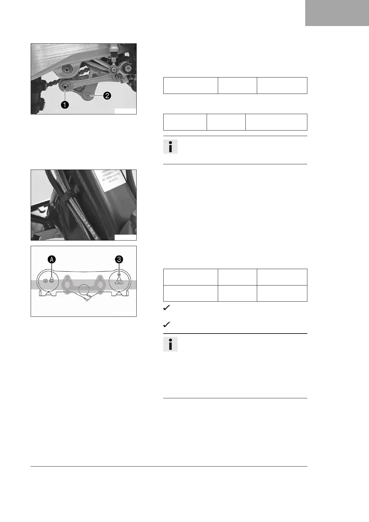
F01064-10
– Position the fork legs and tighten the screws of the triple
clamp.
Guideline
Screw, top triple
clamp
M8 17 Nm
(12.5 lbf ft)
Screw, bottom
triple clamp
M8 12 Nm (8.9 lbf ft)
Air bleeder screw
3
of the right fork leg is positioned
to the front.
Valve
A
of the left fork leg faces the front.
Info
Grooves are milled into the side of the upper end of
the fork legs. The second milled groove (from the
top) must be flush with the upper edge of the upper
triple clamp.
The air suspension is located in the left fork leg.
The pressure and rebound damping is located in
the right fork leg.
 Loading...