TRANSMISSION
B1830,B2230,B2530,B3030, WSM
3-M27
8. PTO SYSTEM (HYDRAULIC PTO CLUTCH MODEL)
[1] STRUCTURE
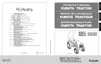
The PTO shift lever (1) is located at left side fender.
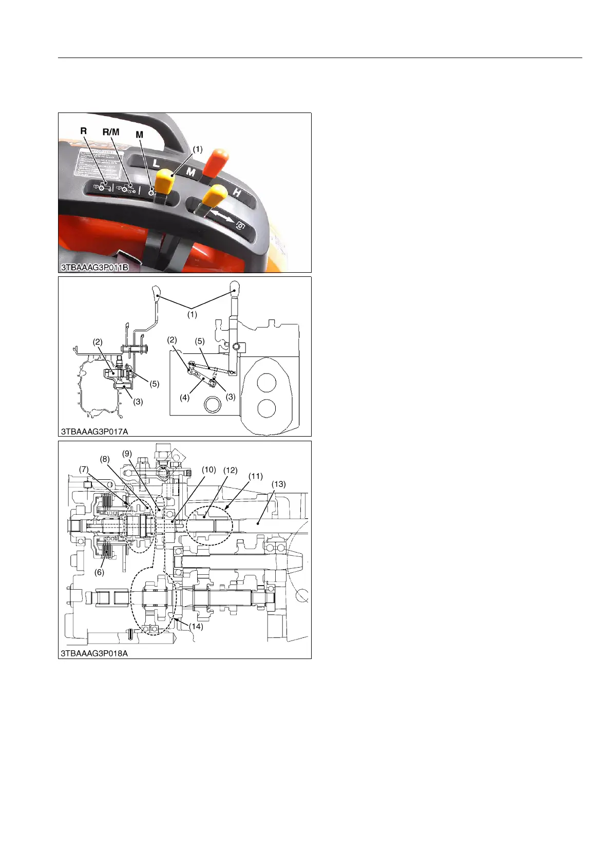
The PTO shift lever (1) and the PTO shift arm (2) are
linked with the control rod (5).The PTO shift arm (2) and
the rear PTO arm (3) linked with the rear PTO control
plate.
The PTO shift arm (2) shifts the PTO shifter (8).
The rear PTO arm (3) shifts the rear PTO shifter (12).
PTO gear section consists of four sections.
The first section is independent PTO section.
The second section is PTO position selection
section.
The third section is mid-PTO selection section.
The fourth section is rear PTO rotation prevention
section.
In this section, when the PTO shift lever is set to
"Mid-PTO" shifter slides to the front side and shifter
meshes to the housing.
The rear PTO shift does not rotate at this "Mid-PTO"
position.
9Y1210003TRM0027US0
(1) PTO Shift Lever
(2) PTO Shift Arm
(3) Rear PTO Arm
(4) Rear PTO Control Plate
(5) Control Rod
(6) Independent PTO Clutch
(7) PTO Position Selection
Section
(8) PTO Shifter
(9) 25T Mid PTO Gear
(10) PTO Clutch Shaft
(11) Rear PTO Rotation
Prevention Section
(12) Rear PTO Shifter
(13) 8T Rear PTO Shaft (B1830,
B2230, B2530)
10T Rear PTO Shaft (B3030)
(14) Mid PTO Selection Section
R: REAR PTO Position
R/M:REAR PTO / MID PTO
Position
M: MID PTO Position
 Loading...