TRANSMISSION
B1830,B2230,B2530,B3030, WSM
3-S38
(2) Main Gear Shift Section
Steps, Brake Rods, Hydraulic Pipes, Sub-Frames and Wiring
Harness
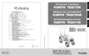
1. Remove the steps (1) and the brake springs.
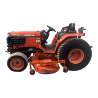
2. Disconnect the connectors from the HST neutral switch, the
PTO switch and the PTO valve switch. Move the wiring harness
to the engine side.
3. Disconnect the hydraulic suction pipe (9) and the hydraulic
delivery pipes (2), (5). Loosen the pipe bands.
4. Remove the snap pins and disconnect the brake rods (8), (11).
5. Remove the sub-frame mounting bolts (7) and the sub-frames
(6), (10).
6. Hook the transmission assembly.
7. Remove the main frame mounting bolts and the main frame (4).
8. Separate the transmission assembly from the tractor main
frame (4).
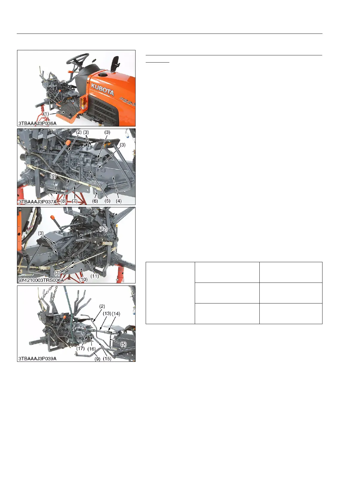
9. Remove the spring pins from the propeller shaft (13).
(When assembling)
Connection of couplings
• Set the rear wheels to the tractor.
• Firstly install the coupling between the front axle pinion shaft
and the front wheel drive shaft under the engine.
• Install the coupling and the propeller shaft to the clutch shaft.
• Secondly align the spline between the front wheel drive shaft
and the universal joint.
• Thirdly, push the transmission assembly slowly to the main
frame side, and align the spline between propeller shaft and the
first shift shaft. Align the universal joint and the front wheel drive
shaft (17).
• Fourthly, install the split pins (16) from the down side.
9Y1210003TRS0047US0
Tightening torque
Main frame mounting bolt
for aluminum (M12)
62.8 to 72.5 N·m
6.4 to 7.4 kgf·m
46.3 to 53.5 lbf·ft
Main frame mounting nut
for aluminum (M12)
62.8 to 72.5 N·m
6.4 to 7.4 kgf·m
46.3 to 53.5 lbf·ft
Main frame mounting bolt
for ordinary material (M12)
77.5 to 90.2 N·m
7.9 to 9.2 kgf·m
57.2 to 66.5 lbf·ft
(1) Step
(2) Hydraulic Cylinder Delivery Pipe
(3) Bolt
(4) Main Frame
(5) PTO Valve Delivery Pipe
(6) Sub-frame, R.H.
(7) Bolt
(8) Brake Rod, R.H.
(9) Hydraulic Suction Pipe
(10) Sub-frame, L.H.
(11) Brake Rod, R.H.
(12) Wiring Harness
(13) Propeller Shaft
(14) Coupling
(15) Drive Shaft
(16) Split Pin
(17) Front Wheel Drive Shaft
 Loading...