CABIN
B1830,B2230,B2530,B3030, WSM
10-M22
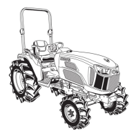
[2] BLOWER RELAY, COMPRESSOR RELAY, THERMO SWITCH
AND PRESSURE SWITCH
Remove the inner roof and the relays are visible at
the left side pillar of the cabin ceiling: blower relay (1)
and compressor relay (2). When the blower fan is
adjusted for the air flow rate, the blower relay (1) is
activated by a signal from the fan switch on the control
panel.
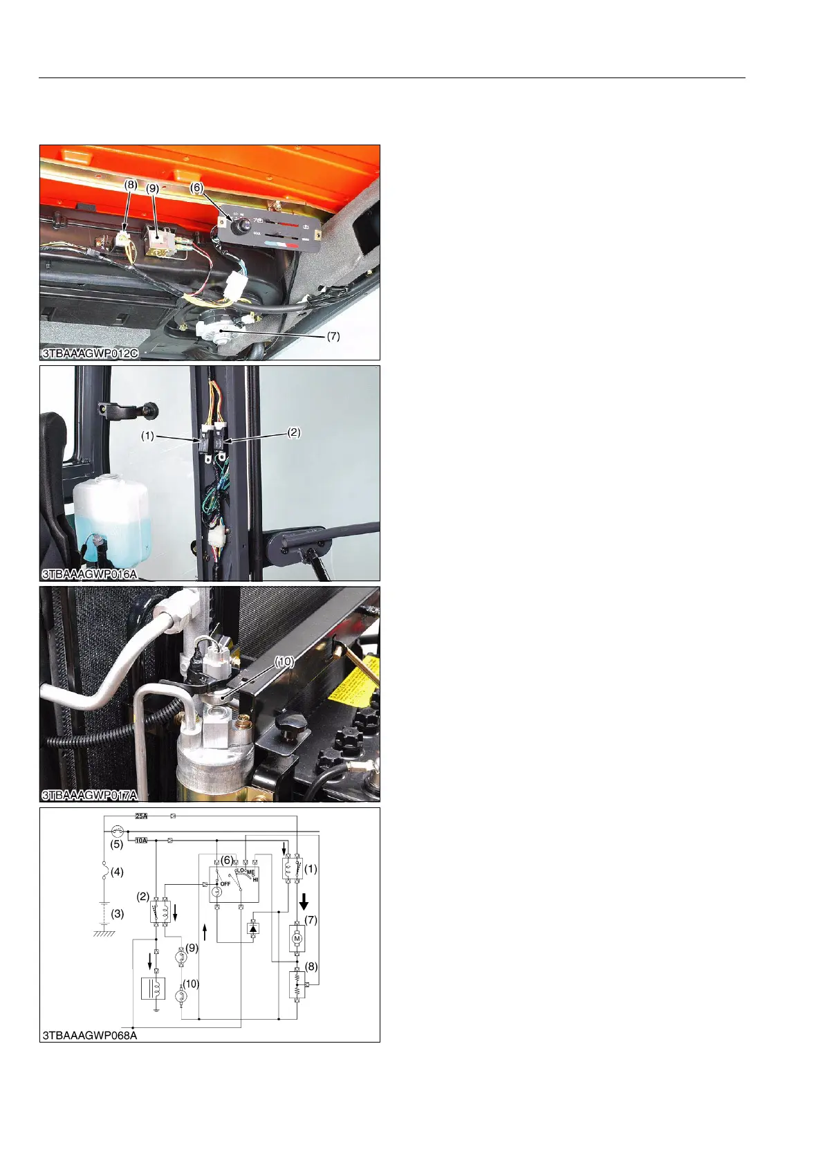
Among the air conditioner components, current flows
to the blower motor (7) and magnetic clutch. If all of
these current were to be passed through the main switch
(5) and supplied, the current would be too large for the
main switch (5). This could cause the main switch to burn
out. If the current were to be passed directly from the
battery (3), forgetting to turn off the blower motor (7)
could result in a discharged battery (3).
To protect against such trouble, relays have been
provided. These relays have been made so that when
current flows through its coil, the contacts close to supply
the power from the battery (3). By employing these
relays, the current flowing through the main switch (5)
has been decreased as only a small current is required
to actuate the relay. Thus there will be no danger of
burning out the switch contact, and when the main switch
(5) is opened, the relay contact will open at the same
time. This action stops the current flow in the air
conditioner circuit so that there will also be no chance of
the battery discharging.
9Y1210003CAM0028US0
(1) A/C Blower Relay
(2) Compressor Relay
(3) Battery
(4) Slow Blow Fuse
(5) Main Switch
(6) A/C Blower Switch
(7) A/C Blower Motor
(8) A/C Blower Resistor
(9) Thermo Switch
(10) Pressure Switch
 Loading...