Do you have a question about the Kubota D1703-B and is the answer not in the manual?
Instructions to prevent fires related to fuel, sparks, and battery gases.
Precautions regarding battery electrolyte (sulfuric acid) to prevent burns and eye damage.
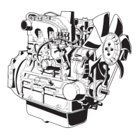
Description of the cylinder block, its construction, and benefits for cooling and noise reduction.
Details on the cross-flow intake/exhaust ports, combustion chamber type (E-TVCS), and components like injection nozzle and glow plug.
Explanation of piston shape, ring installation, and the function of each ring type.
Description of the NIPPONDENSO OPD mini nozzle, its flat-cut design, and heat seal.
Explanation of the all-speed governor's function in maintaining constant engine speed by adjusting fuel supply.
Description of the alternator's function in generating 3-phase current and rectifying it.
Description of the alternator's output current, voltage, and rotational speed characteristics.
Precautions when checking the compact alternator with IC regulator, including terminal connections and battery usage.
Procedure for disassembling and assembling the starter motor, including brush holder and armature.
Procedure for removing the pulley and fan from the alternator.
Troubleshooting guide for engine not starting, with probable causes and solutions.
Specifications for cylinder head surface flatness, top clearance, and gasket thickness.
Schedule for regular engine inspections and maintenance tasks based on operating hours.
Procedure for checking and adjusting valve clearance, including timing marks and piston position.
Procedure for checking and adjusting compression pressure, including tester usage and allowable limits.
Steps for checking and adjusting compression pressure, including tester use and data interpretation.
Procedure for removing the cylinder head cover, injection pipes, glow plugs, and nozzle holders.
Steps for removing the rocker arm assembly, push rods, and intake/exhaust manifold.
| Engine Model | D1703-B |
|---|---|
| Type | Diesel |
| Number of Cylinders | 3 |
| Aspiration | Natural |
| Fuel System | Direct injection |
| Cooling System | Water-cooled |
| Starting System | Electric starter |
| Rotation | Counterclockwise (viewed from flywheel side) |
| Engine Type | 4-cycle, water-cooled |
| Bore x Stroke | 87 mm x 92.4 mm |
| Lubrication System | Forced lubrication |
| Displacement | 1.647 L (100.5 cu. in) |
| Compression Ratio | 23:1 |