1. TRACTOR PREPARATION:
MOUNT KIT INSTALL
TOOLS REQUIRED:
• 13/16” SAE wrench or socket
• Two (2) each, 12mm and 14mm Metric wrenches or sockets
1.1 Lift the engine bonnet to the upward position and move the seat
into its forward position.
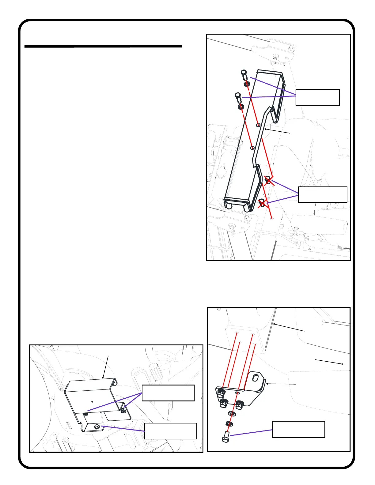
1.2 Per Figure 1.2, remove and discard the two bolts from the lower
center of the ROPS (Roll-Over Protective Structure). Remove
and retain the washers from the bolts. Install the Rear Center
Mount and secure it with the 2 (two) 9/16-18 bolts from the
hardware kit and the washers from the tractor.
Tighten the 9/16-18 bolts to 110 - 132 ft-lbs (149 - 179 N-M).
QTY HARDWARE
2 9/16-18 x 1-1/4” Hex Head Bolts (remove and discard)
2 9/16-18 x 2-1/4” Hex Head Bolts
2 9/16” Split Lock Washers (re-use from tractor)
1.3 Per Figure 1.3, install the rear mounts to the side of the ROPS
using 4 (four) M10 bolts, split washers and flat washers per side,
supplied in the hardware kit.
Install Finger Tight at this time.
QTY HARDWARE
8 M10 x 1.25mm x 20mm Hex Head Bolts
8 M10 Flat Washers
8 M10 Split Lock Washers
1.4 Per Figure 1.4, on each side of the vehicle remove and retain the
two M8 nuts securing the fender to the frame and one M10 bolt
securing the side strut to the frame. NOTE: the right side has one
M10 bolt into a threaded hole in the frame; the left side has one
M10 bolt and nut.
1.5 Place the front mounts against the frame and secure them with
the retained hardware.
Tighten the M8 nuts to 17.4 - 20.2 ft-lbs (23.6 - 27.4 N-M).
Tighten the M10 bolts to 35.5 - 41.2 ft-lbs (48.1 - 55.8 N-M).
QTY HARDWARE
4 M8 Hex Nut with Captive Washer (re-use from tractor)
2 M10 x 1.25mm x 20mm Hex Head Bolts
(re-use from tractor)
1 M10 Hex Nut (re-use from tractor)
Fig. 1.2 : Rear Center Mount
REAR CENTER MOUNT
9/16-18 x 2-1/4”
QTY: two (2)
9/16-18 x 1-1/4”
(remove & discard)
Fig. 1.3: Rear Lower Mounts (right side shown)
M10 x 20mm
QTY: four (4) per side
Rear Lower
Mount
Tractor ROPS
M8 Hex Nuts
QTY: two (2) per side
M10 x 20mm
QTY: one (1) per side
FRONT MOUNT
Fig. 1.4: Front Mounts (right side shown)
Front
of Tractor
P. 5 of 14
 Loading...