1-S39
GL6000, GL7000, GL9000, GL11000, WSM
ENGINE
Main Bearing Case Assembly
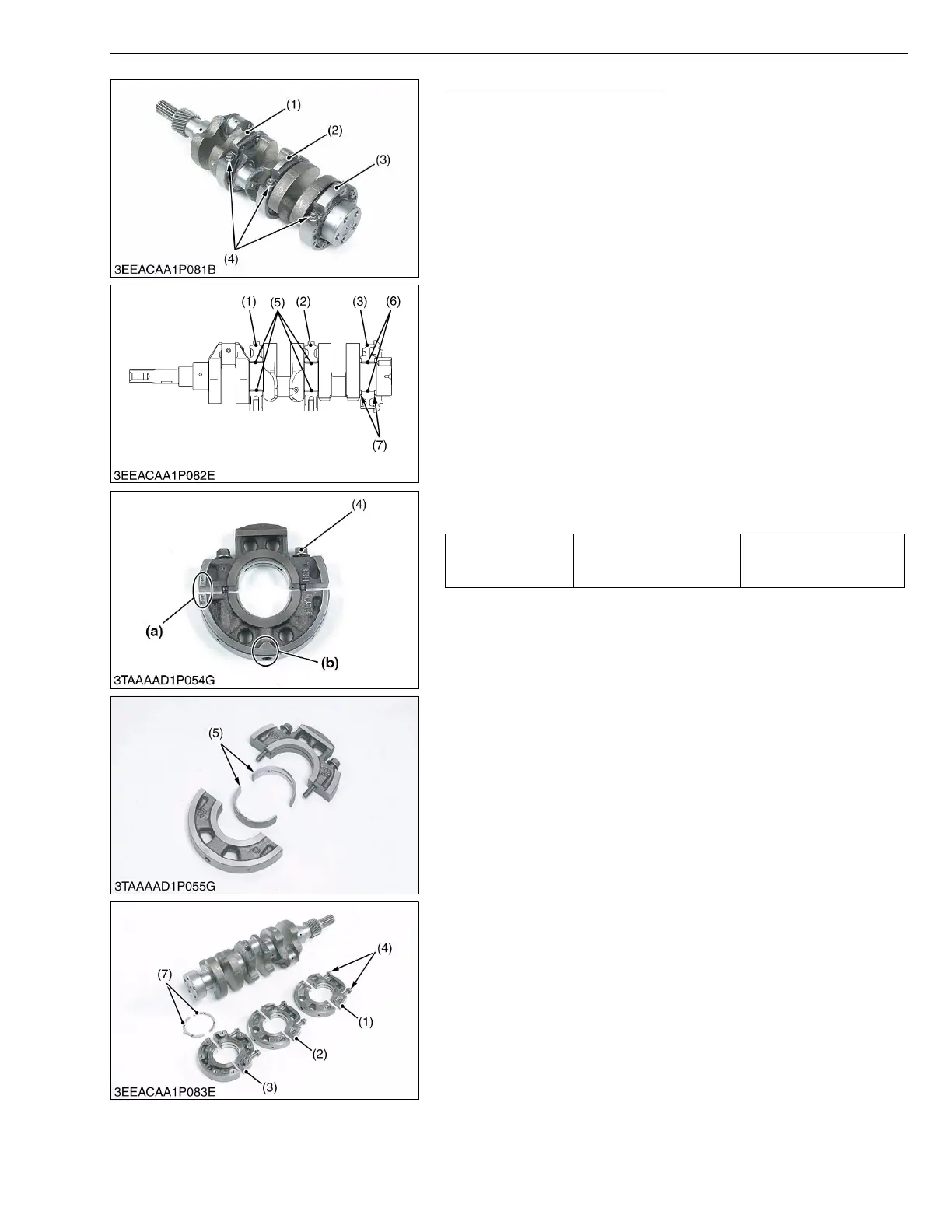
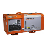
1. Remove the two main bearing case screws 1 (4), and remove the
main bearing case assembly 1 (1) being careful with crankshaft
bearings 3 (5).
2. Remove the main bearing case assembly 2 (2) and the main
bearing case assembly (3) as above. Keep in mind, however,
that the thrust bearing (7) is installed in the main bearing case
assembly (3).
(When reassembling)
• Clean the oil passage in the main bearing cases.
• Apply clean engine oil on bearings.
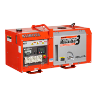
• Install the main bearing case assemblies in original positions.
Since diameters of main bearing cases vary, install them in order
to marking (b) (1 for GL6000, GL7000 and 1, 2 for GL9000,
11000) from the gear case side. (Refer to the figure.)
• Match the alignment number (a) on all main bearing case
assembly 1.
• Do the same for the main bearing case assembly 2 (2) and the
main bearing case assembly (3) too.
• When installing the main bearing case 1 and 2, face the mark
"FLYWHEEL" to the flywheel.
• Install the thrust bearing (7) with its oil groove facing outward.
• Make sure that the main bearing case moves smoothly after
tightening the main bearing case screw 1 to the specified torque.
W1034602
Tightening torque Main bearing case screw 1
12.7 to 15.7 N·m
1.3 to 1.6 kgf·m
9.4 to 11.6 lbf·ft
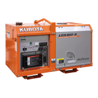
(1) Main Bearing Case Assembly 1
(2) Main Bearing Case Assembly 2
(3) Main Bearing Case Assembly
(4) Main Bearing Case Screw 1
(5) Crankshaft Bearing 3
(6) Crankshaft Bearing 2
(7) Thrust Bearing
(a) Alignment Number
(b) Marking (1 or 2)




 To Next Page