GR1600EC, WSM FRONT AXLE
4-S6
[3] DISASSEMBLING AND ASSEMBLING
(1) Front Axle Assembly
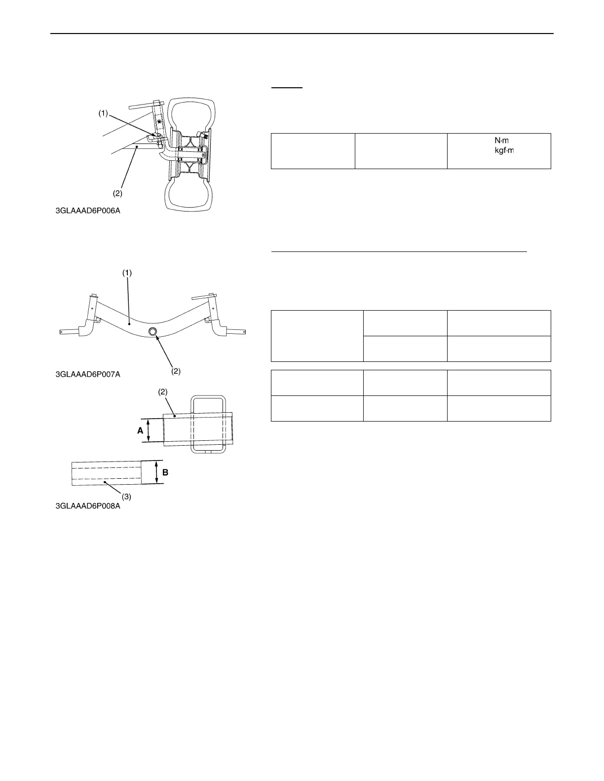
Tie-rod
1. Remove the tie-rod mounting locking nut (1).
2. Remove the tie-rod (2).
(When reassembling)
[4] SERVICING
Clearance between Center Pin Boss and Center Pin Collar
1. Measure the center pin boss (2) I.D. with a cylinder gauge.
2. Measure the center pin collar (3) O.D. with an outside
micrometer and calculate the clearance.
3. If the clearance exceeds the allowable limit, replace them.
Tightening torque
Tie-rod mounting
locking nut
49.9 to 54.2
5.09 to 5.53
36.8 to 40.0 ft-lbs
(1) Tie-rod Mounting Locking Nut (2) Tie-rod
0000009463E
Clearance between
center pin boss and
center pin collar
Factory spec.
0.109 to 0.200 mm
0.00430 to 0.00789 in.
Allowable limit
0.210 mm
0.0828 in.
Center pin boss I.D. (A) Factory spec.
25.400 to 25.430 mm
1.00000 to 1.00118 in.
Center pin collar O.D.
(B)
Factory spec.
25.230 to 25.291 mm
0.99329 to 0.99570 in.
(1) Front Axle Frame (3) Center Pin Collar
(2) Center Pin Boss
0000009464E